Week 8 - Challenge 4 - Bumper
AIM:
To create the Bumper Plastic component through the given Class-A surface.
OBJECTIVES:
To begin with, the tooling axis for the given Class-A Surface should be created meeting the requirements of the draft angle and at the end perform the Draft analysis on the model.
Take the Thickness of the component to be 3 mm
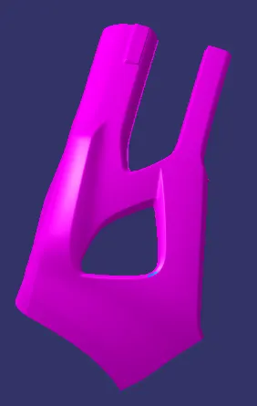
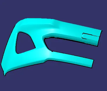
GIVEN CLASS A SURFACE:
CREATION OF TOOLING AXIS:
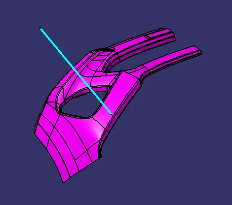
First we need to check the component that is create based on normal axis (compass) it realated or not.
For this we need to create a line for line we need a point
place the point where surface is flat to check the draft analysis and create the line It should perpendicular to the component
Then check the normal axis and also the draft analysis passes or not.
If it is passing we can go with normal axis which in softwate by default
if it is not we need to go with making the line (tooling axis) with poin to normal to the surface that surface should be flat.
And then do the draft analysis with the refrence of tooling axis what we made.
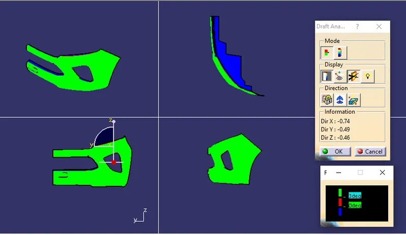
Draft Analysis: Draft Analysis is done to check whether the part created can be removed easily from the cavity easily. It is done by giving different color zones which shows any deviation from the specified draft angle and direction.
Then give the solid part as material in customize view parameters than go for draft analysis
which is in tool bar analysis , feature draft analysis .
Then select the surface as input,and then pic the compass , and placed in then tooling Axis what we created,
And activate the compass by clicking the compass icon in that draft analysis dialogue box .
Then check the draft analysis with the help of color cooding in color showing dialogue box.
Where ever it passes it shows in green in color it shows the draft angle is perfect
If it shows red in color it shows that the no draft that is 0 deg in it.
If it shows blue color it shows that it is less than 0 deg.
In setting the color cooding based upon the costomer need or for our refrence.
Draft analysis is that check the tooling axis with the component it will pass or not , when we going for injection molding it should have proper draft angle in it.
In draft analysis it shows that where the component passes or not in injection molding with the help of tooling axis
In CATIA Software the tool which is called draft analysis in that with the help of compass we will analysis the draft or in the propre direction
Where ever it passes it shows in green in color it shows the draft angle is perfect
If it shows red in color it shows that the no draft that is 0 deg in it.
If it shows blue color it shows that it is less than 0 deg.
Sides of the part that appear parallel with the direction of draw (The axis of the cored position (hole) or insert is parallel to the up and down movement of the mold as it opens and closes) are typically angled slightly with (draft) to ease release of the part from the mold. Insufficient draft can cause deformation or damage.
All the color and values setting manually by the design engineer with the help of customer requirements.
Minimum thickness of the plastic component is 2.5 mm it an universal dimension
Because the thickness of the plastic component beyond 2.5 mm it is difficult to produce in injection molding and also the plastic component not be strength it will lose its property.
For the injection molding component it must have minimum of 3deg or more than that.
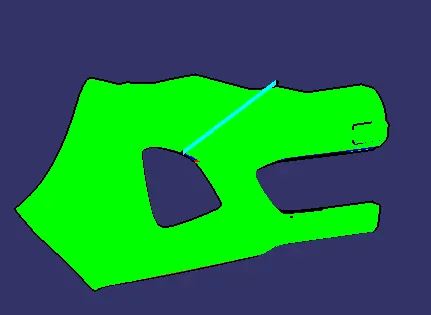
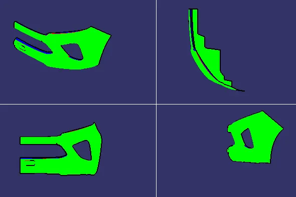
DRAFT ANLYSIS OF CLASS A SURFACE:
CLASS B SURFACE:
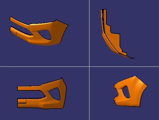
CLASS C SURFACE:
CLASS A+CLASS B+CLASS C SURFACE:
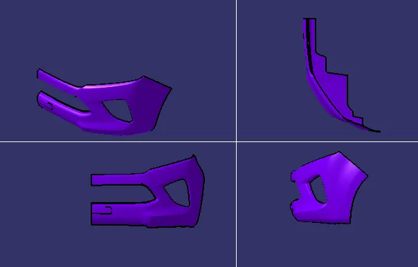
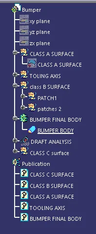
FINAL PLASTIC BODY:
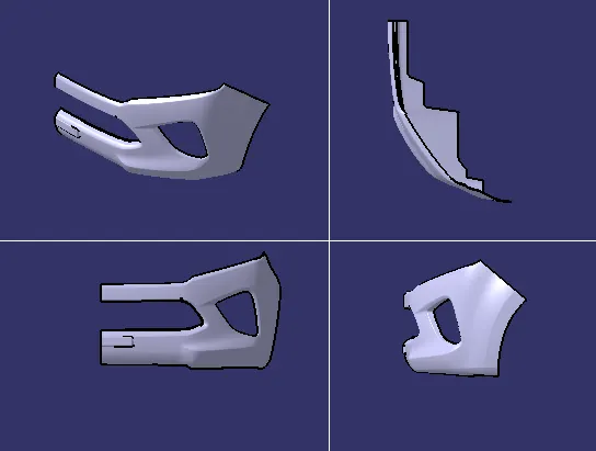
DRAFT ANALYSIS OF PLATIC BODY: