Week 8 - Challenge 4 - Bumper
AIM : To create the Bumper Design Plastic component through the given Class-A surface.
Objective
- To create a tooling direction.
- To perform draft analysis for given A-Surface and prepare the final close body.
- To design the Bumper plastic component by creating the B-Surface and C-Surface using the given Class-A surface.
- Take the Thickness of the component to be 3 mm.
INTRODUCTION :-
The input of the product designer is in the form of the A-class surface. The job of the product designer is to create the B and C surfaces keeping all the aspects for the mold.
1)CLASS A SURFACE FEASIBILITY CHECK:-
Check the connectivity of the Class A Surface Ensure that there is no gap between the component, using join command. We can visually check it or by clicking boundary command. It has a boundaries outer. Therefore first check completed.
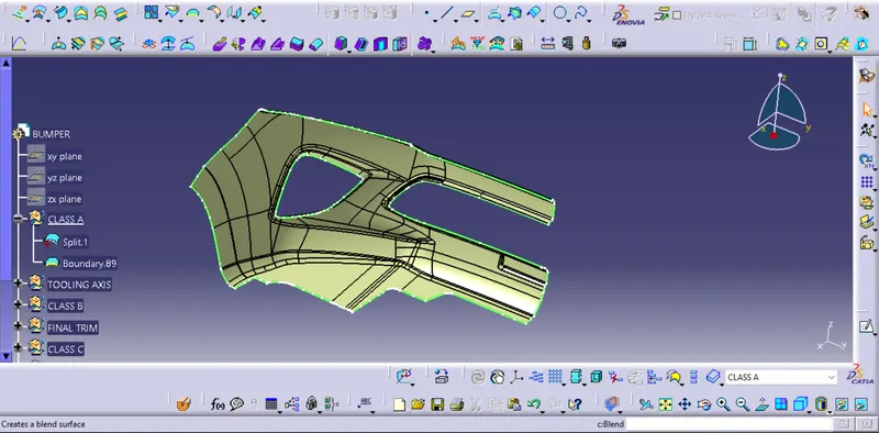
The given A-Surface having No gap as above fig shown. Hence boundary generated at the edges.
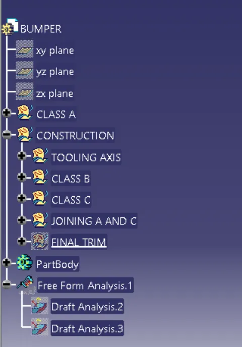
FEATURE TREE:-
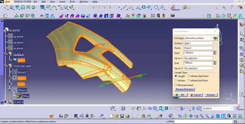
Tooling Direction for Plastic Part :-
- Tooling direction is main consideration for plastic part and mold parts because it defines movement of mold part and possibility of plastic part to come-out from mold part (Core and Cavity).
- In Molding machine arrangement is given to open the mold along a direction which is known as Tooling Direction.
- In other words. The mold is built from two separate halves (Core and Cavity) and tooling direction basically define the direction of mold pulls apart.
- Tooling direction is known as primary direction.
DRAFT ANALYSIS OF CLASS A:-
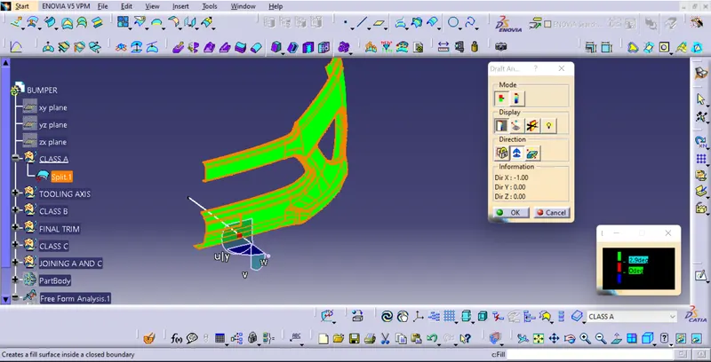
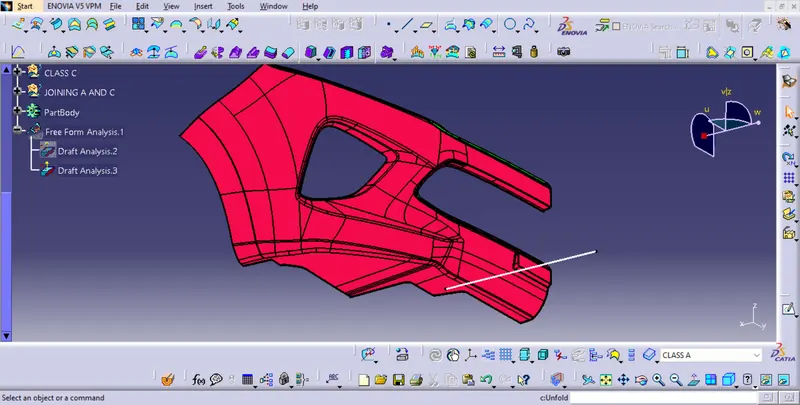
The result shows that the surface is formable or feasible and tooling axis is also correct.
2)Creation of B-Surface:-
Class B surface is created with help of A-Surface by using the Off-set,Trim command,Multi Section,Sweep and Fill command.The first step is offsting the surface by the required thickness. 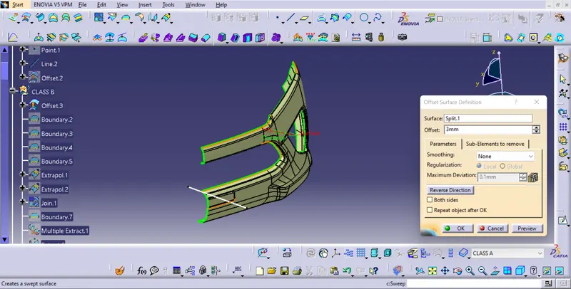
By the offset command some surface may get eleminated we fill those surface by using different commands like multi section surface,sweep,trim,fillet,extrapolate and joined those surfaces with the main surface.
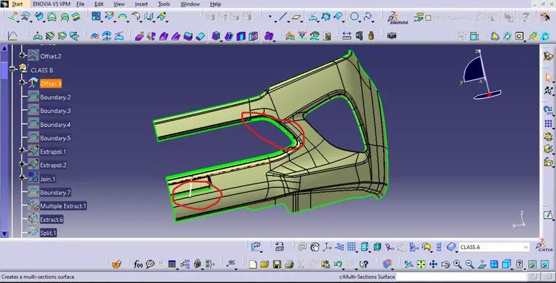
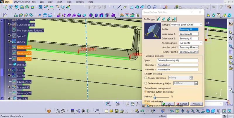
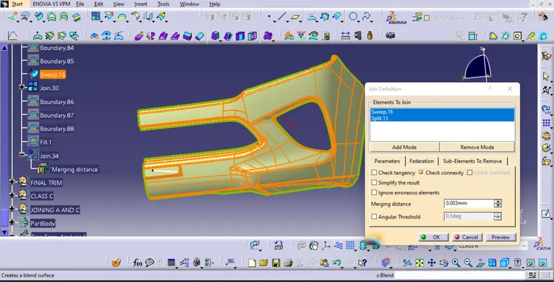
3)CREATING CLASS-C SURFACES:-
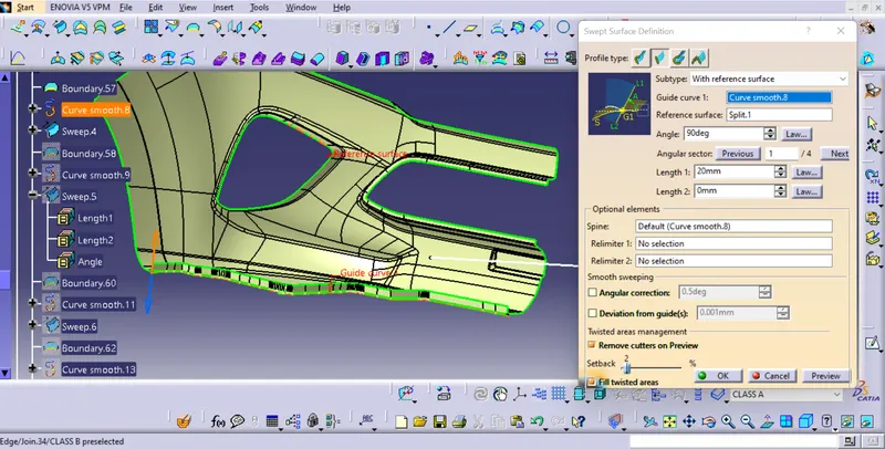
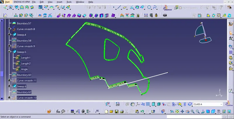
In this model, unlike the earlier models, we have used a parallel tooling axis. Hence we cannot use the ‘with draft direction’ option under sweep.The C surfaces will mostly be created BY reference to surface option some edges are sweeped by 90 degree angle and aome are sweeped by 3 degrees angle.
4)JOINING OF CLASS A AND C:-
5)FINAL TRIM:-
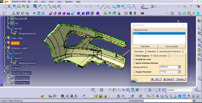
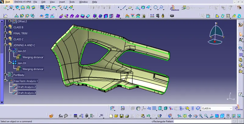
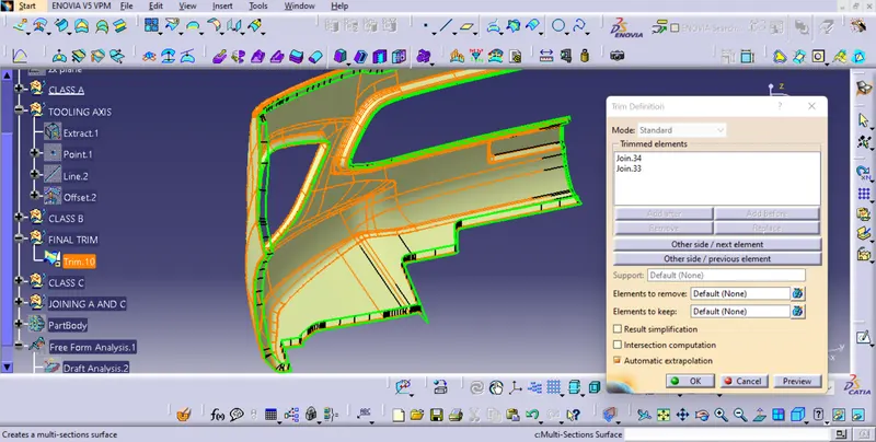
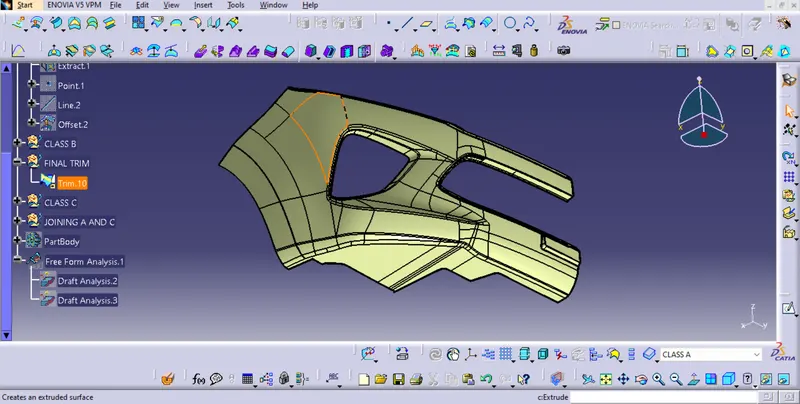
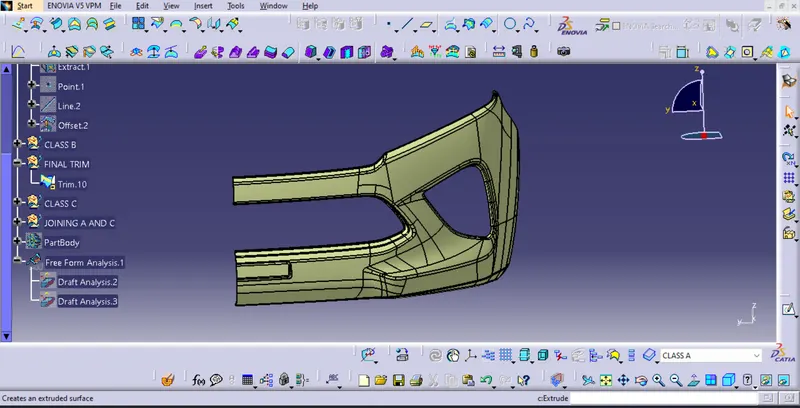
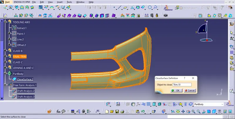
Join A and C is trimmed with class b surface to get the close surface.If the b surface is not intersecting with C the the B surfaec is extapolated to do the trim.We will get the close surface.
6)CLOSE SURFACE:-
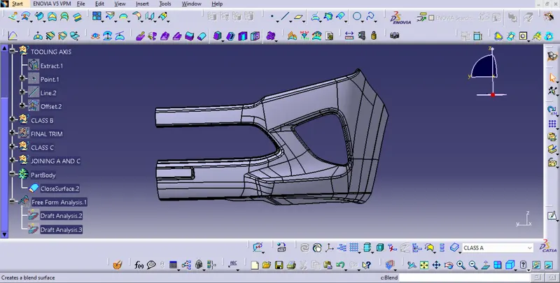
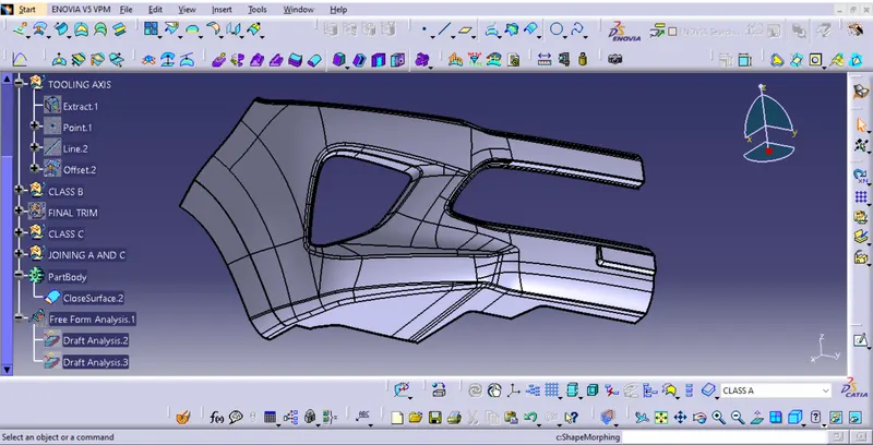
6)DRAFT ANALYSIS OF FINAL OUTPUT:-
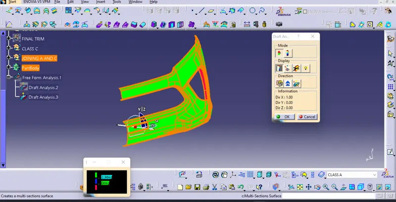
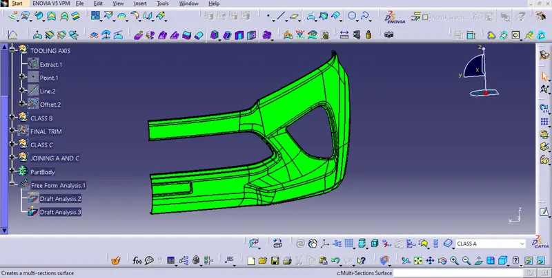
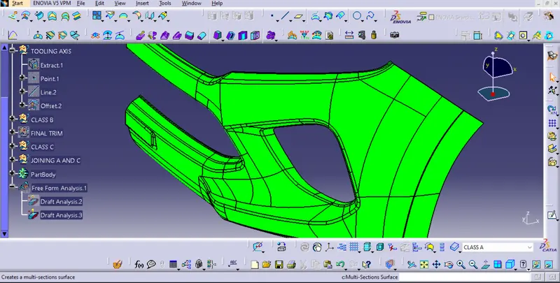
Draft analysis is performed based on colour ranges identifying zones on the analyzed element where the deviation from the draft direction at any point, corresponds to specified values. Minimum draft angle is considered as 3 degree.
Conclusion :-
Thus the Bumper plastic component has been designed using the given class-A surface.