Advanced Sheet Metal Design Using NX Cad Challenge_2_Box Assembly
Title of project:- Advanced sheet metal desing using NX cad challenge 2 Box aseembly.
Objective:-To design a sheet metal box aseebmly using Nx cad metal application.
Introduction:-sheet metal:- Its one of the fundametal forms used in metalworking and it can be cut and bend into a variety of shapes.NX:-its an advanced high-end CAD/CAM/CAE/,which has been owned by siemens PLM Softwere.Mostly it is used for design,analysis,manufacturing.
In this project, the box assembly consist of 3 part
a)box
b)Lid
c)hinge
this project is designed by NX 12 softwere.
Design methodology:-
Design methodology can be explanied by following steps:
Modelling of Box assembly
1) start NX 12 and create new sheet metal model
2)create tab and add flange and hem
3)Use mirror feature to mirror the body
4)Add dimple and use mirror feature
5)Unbend the sheet metal
6)Add bead and use mirror feature
7)Add hem flange at side edges
8)Create new Datum plane and create new sketch
9)Use tab feature to create lid and add flange
10)Create tab,add flange,hem and use breake corner
11)Unbend the newly created sheet
12)Draw sketch,use Normal cutout,rebend and mirror
13)Create new tab, add flange,add hem
14)Add Normal Cutout and Rebend
Discription: The box assembly consists of 3 parts
a)box
b)Lid
c)Hinge
Various steps performed while designing the model are explained as follow
a)box:
box can we designed using following steps
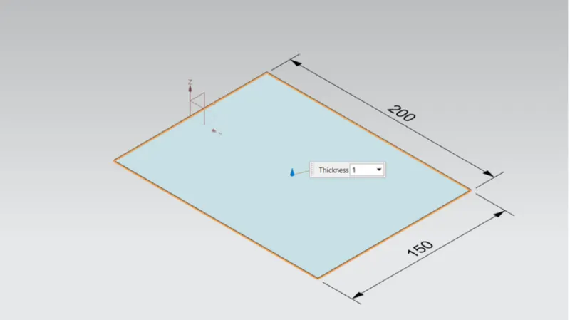
1.Tab:
draw sketch in XY plane and add tab of given thickness.
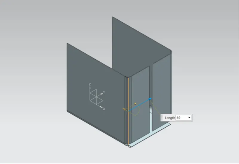
2.flange:
flanges are added normal to xy plane using given dimensions
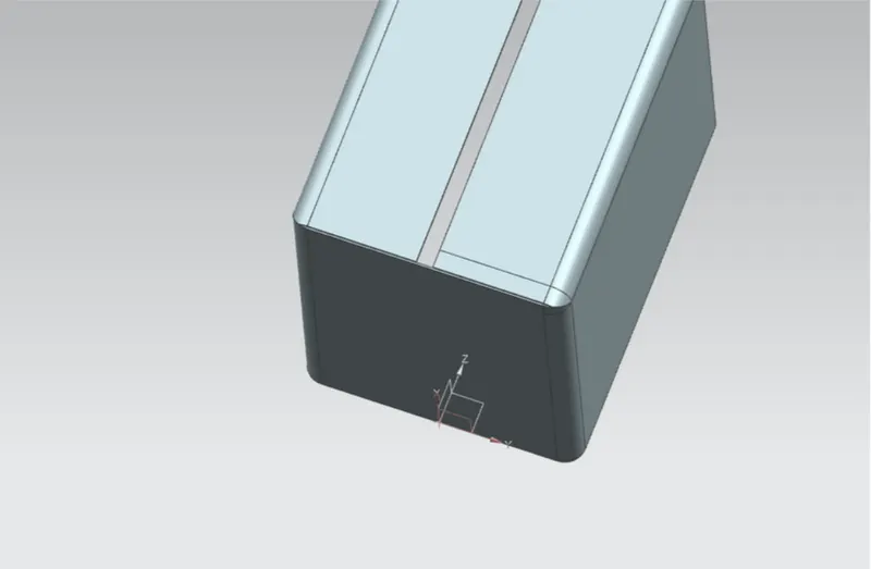
3. closed corner:
By using closed corner command to close the corner
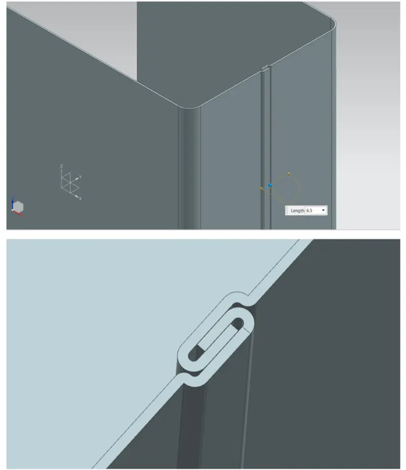
4.Add flange and hem:
flange is added using given dimensions and hem is added at the edge
5.Mirror body and unite:
Use mirror body feature to create the box.After mirroring use unite feature to unite both parts of the box
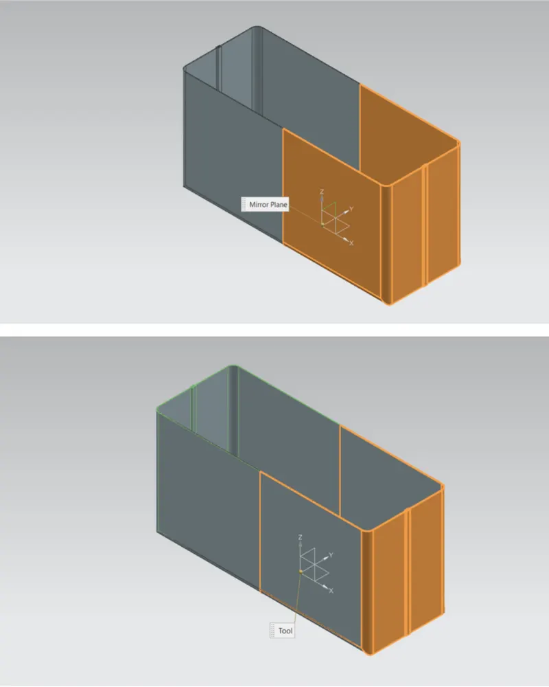
6.Add dimple:
Adddimple on adjecent sides using given dimensions and another dimple at the bottom side
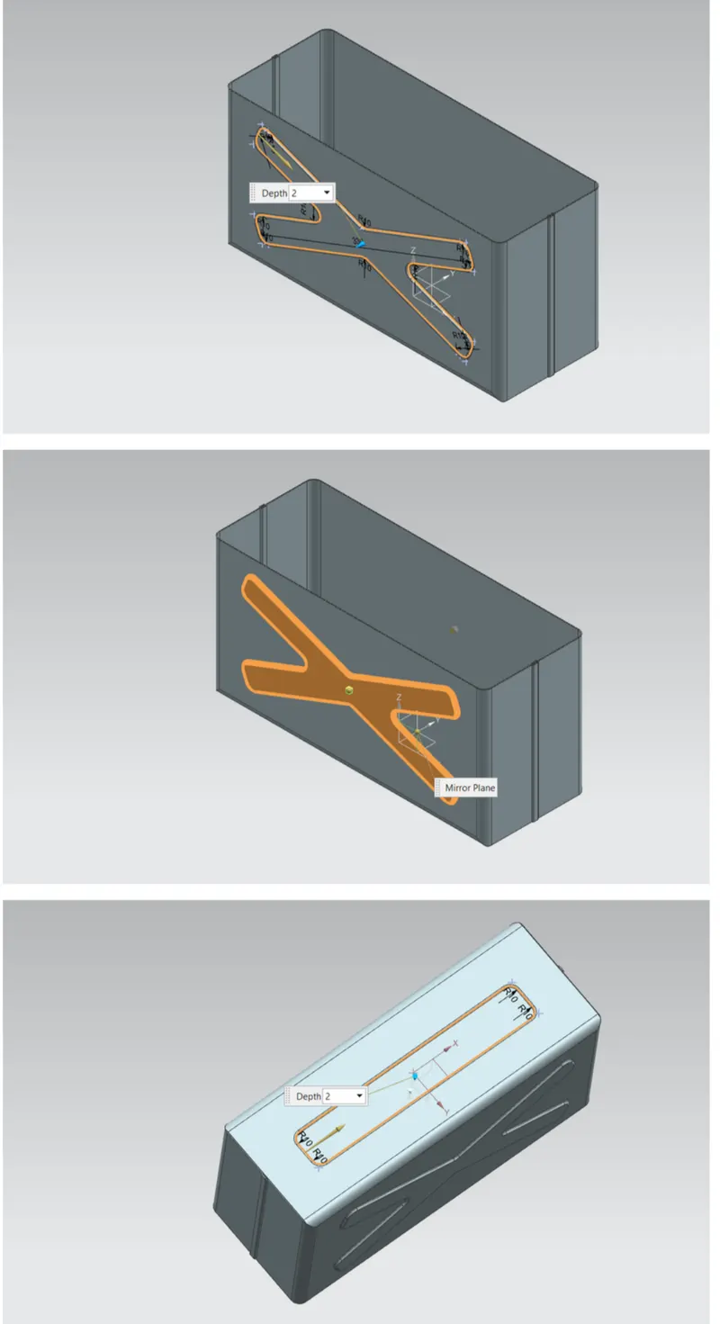
7.Unbend and rebend:
Unbend and rebend the metal sheet
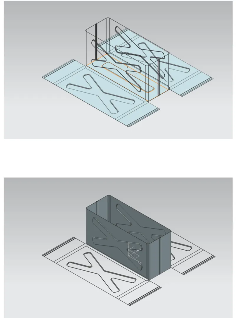
8.Add bead:
Add bead on the bottom plate using given dimensions snd use mirror body feature
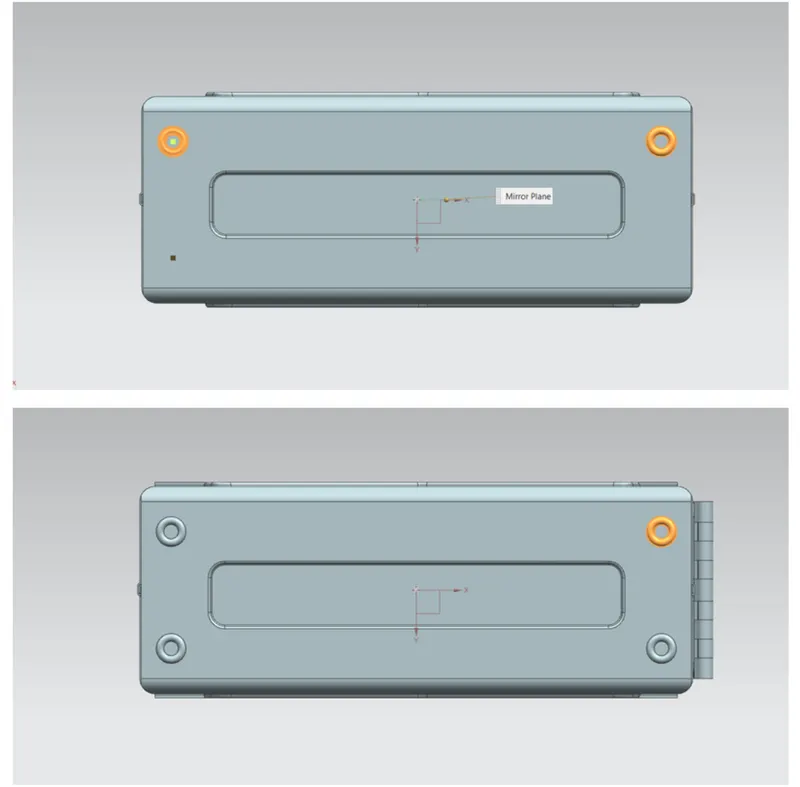
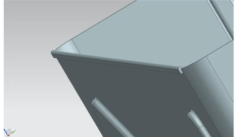
9.Add hem flange:
Add hem along all upper edges of plates using given dimension
b)Lid:
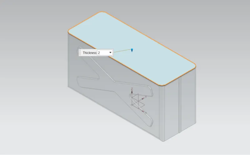
1.Tab:
Create new datum plane. Create new sketch using given dimension and create tab of given thickness
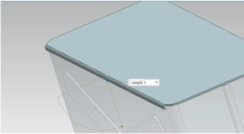
2.Add flange:
Add flange at the top edge of adjecent sides using given dimensions
c)Hinge:
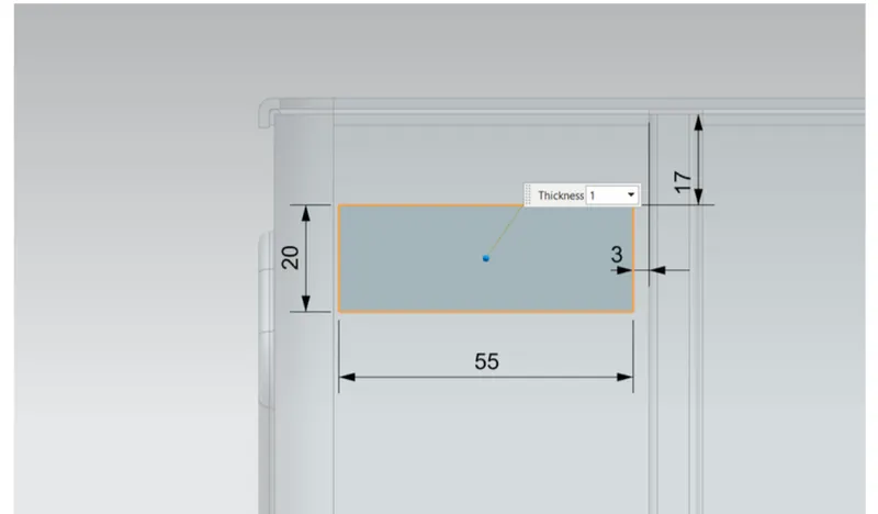
1.Tab:
create new sketch on the back plate and add tab using given dimensions
2.Add flange and hem:-
Add flange and hem on the using given dimensions
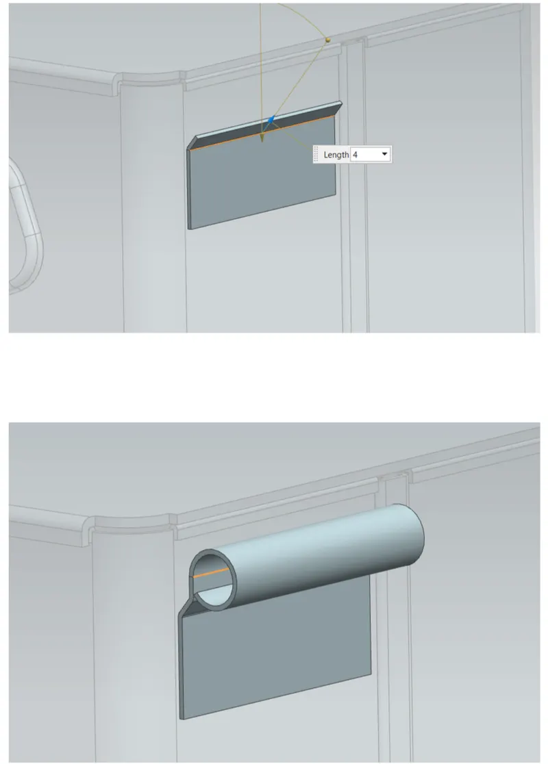
3.unbend:
Unbend the sheet metal to add more details
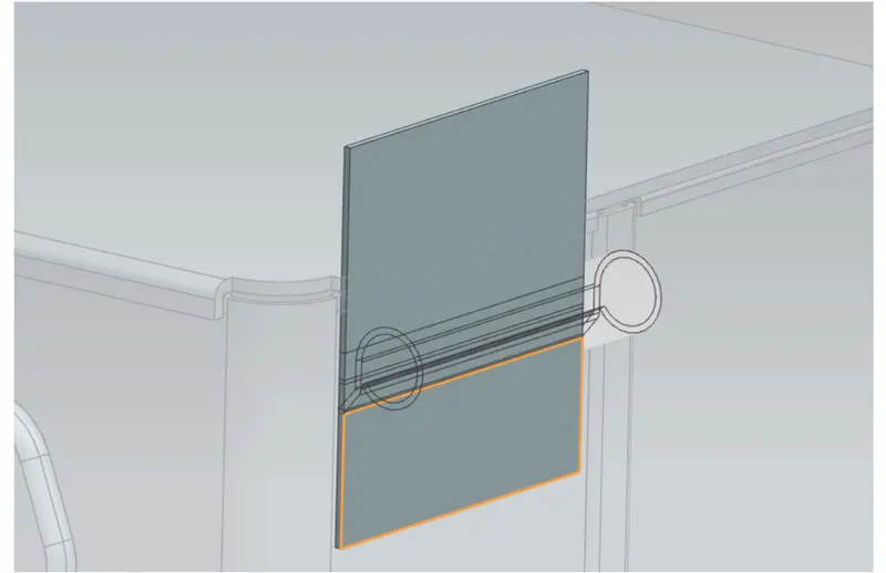
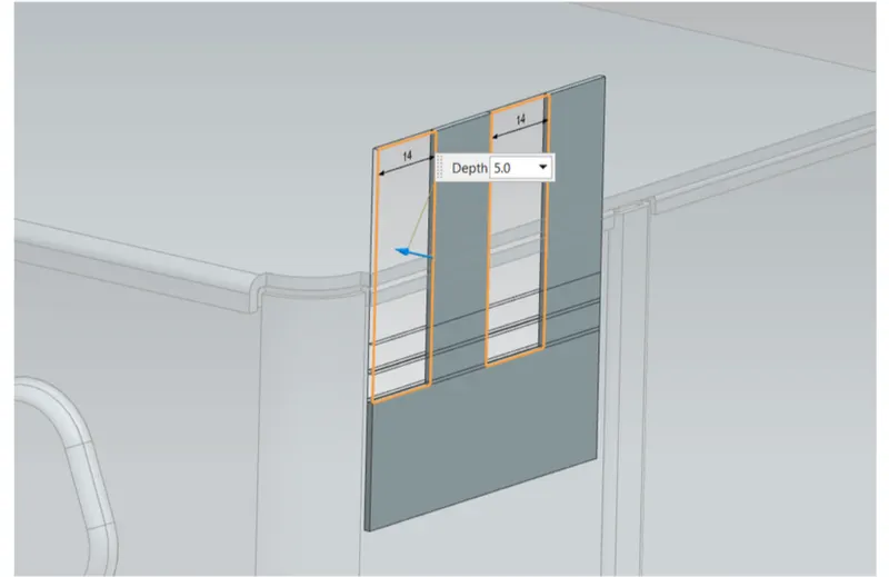
4.Make Normal Cutout:
Draw new sketch on sheet metal surface and use normal cutout feature to create feature to create required cutout
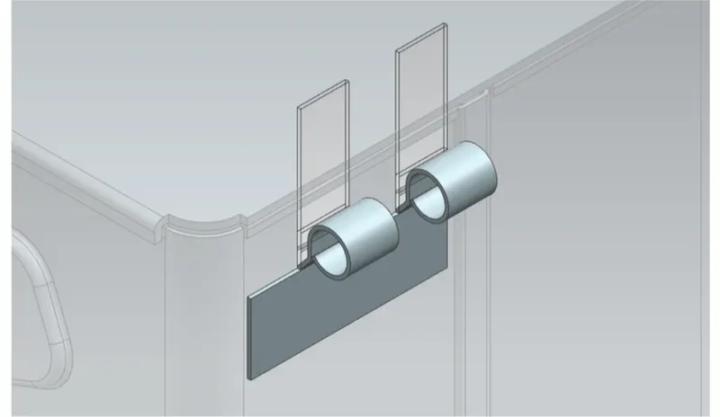
5.Rebend:
Rebend the metal sheet using rebend command
6.Mirror:
Use mirror body feature to mirror the newly created bodies
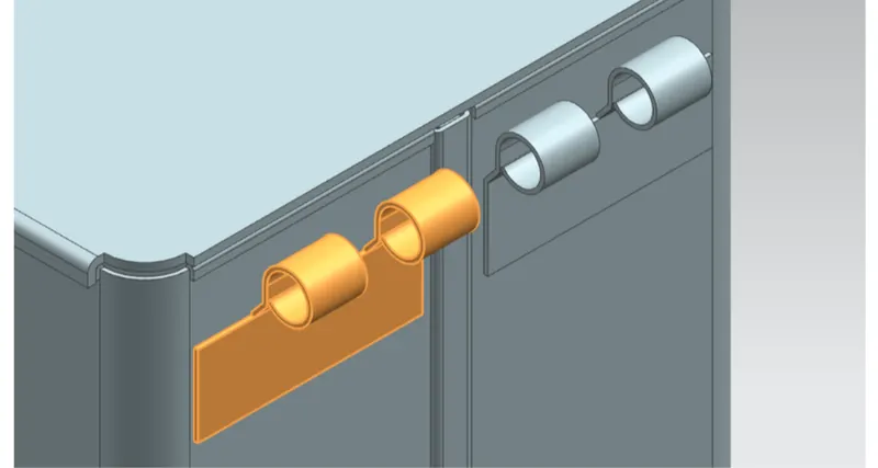
7.Tab:
draw new sketch and create new tab using given dimensions
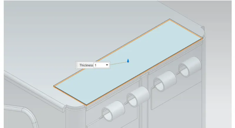
8.Break corner:
Use break corner command to add round shapes at the corner using given dimensions
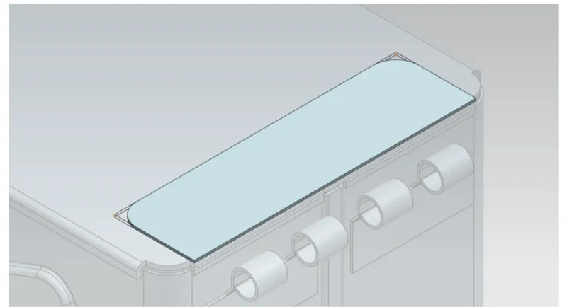
9.Add flanges and hem:
Add flanges and hem using given dionesion
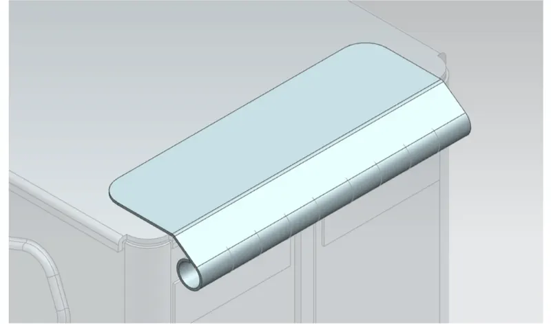
10.Unbend and make normal cutout:
unbend the sheet metal. Draw new sketch and use normal cutout feature to make cut on the sheet metal surface
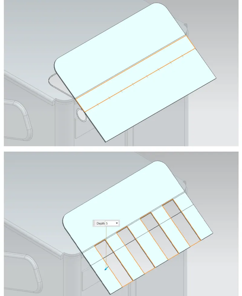
11.Rebend the sheet metal:
`=>`Rebend the sheet metal to create the hinge
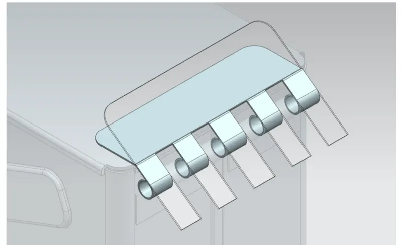
MODEL STANDERD VIEW:
ISOMETRIC VIEW:
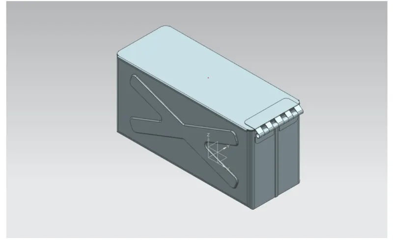
FRONT VIEW:
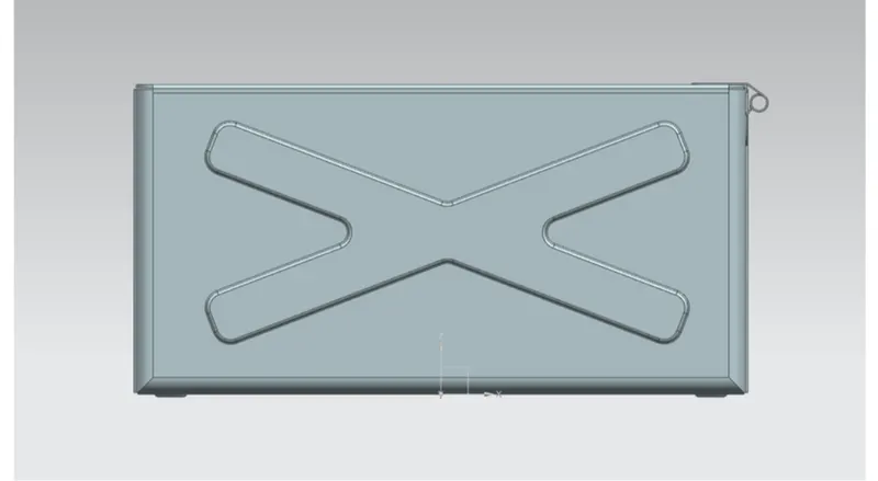
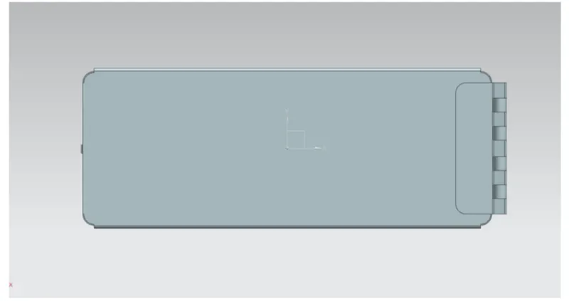
TOP VIEW:
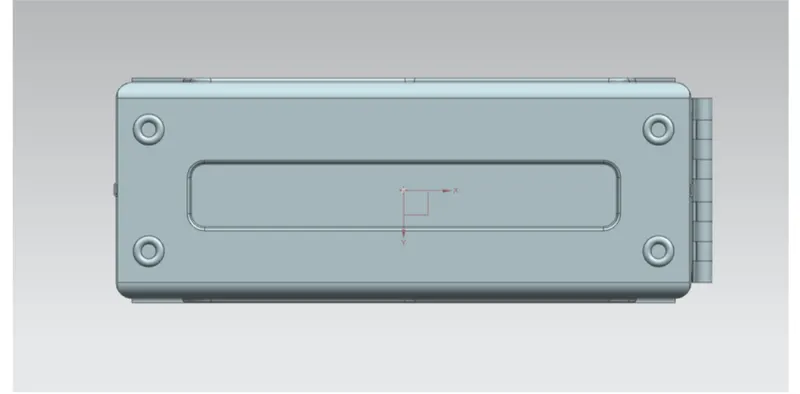
BOTTOM SIDE VIEW:
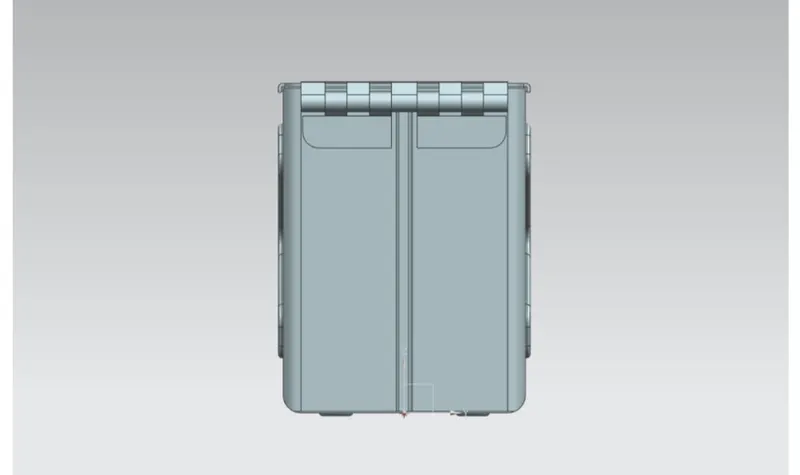
RIGHT SIDE VIEW:
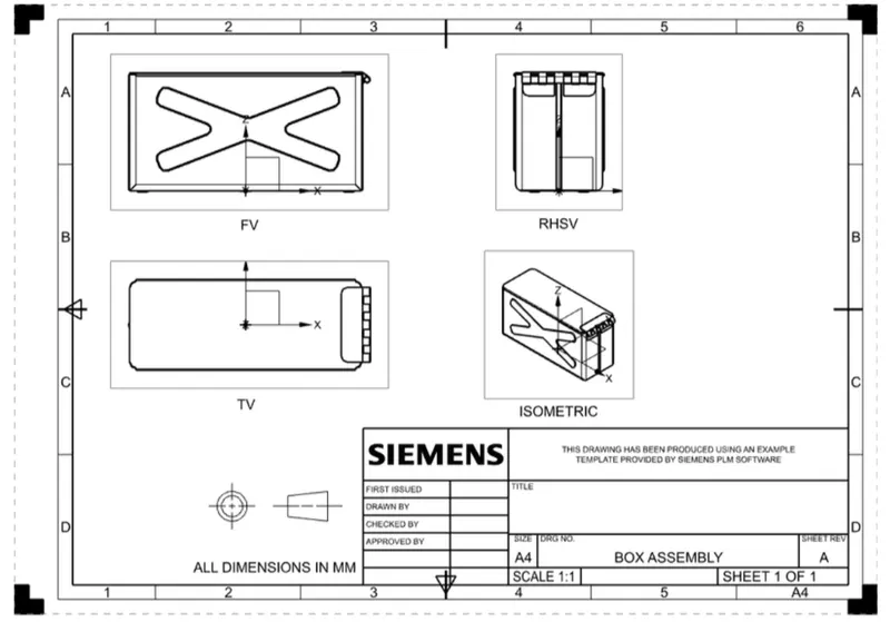
DREWING SHEET IMAGE:
Conclusion:
In this modelling box assembly i learend and practiced lots of command like mirror,breake corner,rebend,hem flange,normal cutout etc.