TO DESIGN A CAR BUMPER BY USING CLASS A SURFACE
AIM:
To design a car bumper Plastic component through the given Class-A surface by creating a tooling axis and draft analysis of the given surface.
DESIGN PROCEDURE:
To setup the class-A surface and to creating a tooling axis
add draft angle
To create a base surface of model
To create a B-surface
To create a C-surface
To use close surface for creating a solid part model
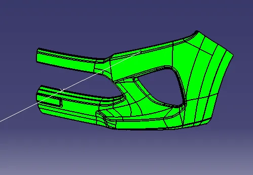
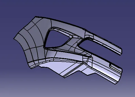
CLASS-A SURFACE:
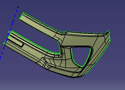
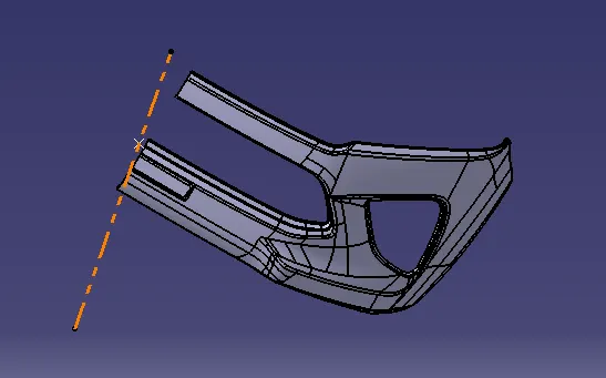
TOOLING AXIS:
Tooling axis can be classified into two methods
- direct method
For this model, to use a line at mid-point of the base of the coin holder
Due to perpendicular walls of the class A surface
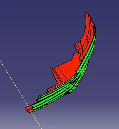
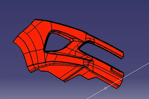
DRAFT ANALYSIS:
The Drafting analysis was performed on the class-A surface by using the Feature Draft Analysis command.
Using this command, the compass was set on the main tooling axis and the Draft angle was changed to 3 degrees.
CREATING CLASS-B SURFACE:
To offset the class-A surface along 3mm for to create a B- SURFCAE.
Surface Gaps can be filled by using a fill tool and multi sectional tool
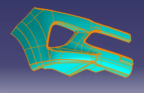
B-SURFACE
CREATING C- SURFACE:
To use multiple extract tool on the class A surface
The extract boundaries can be sweep at 90 degrees to the reference boundaries up to required length
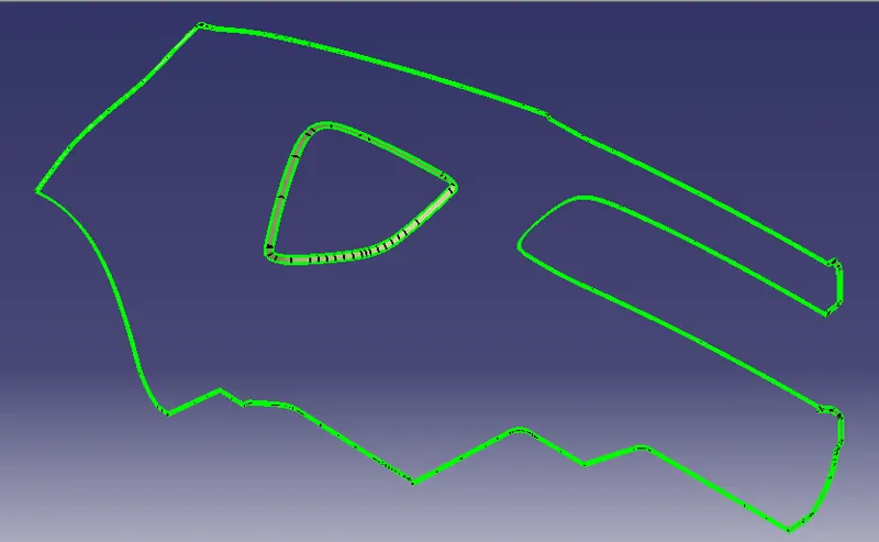
C-SURFACE
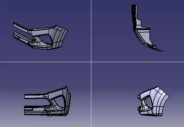
SURFACE MODEL OF A CAR BUMPER:
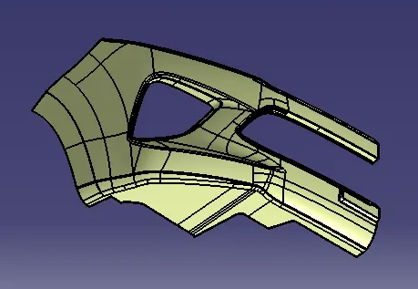
SOLID MODEL OF A CAR BUMPER:
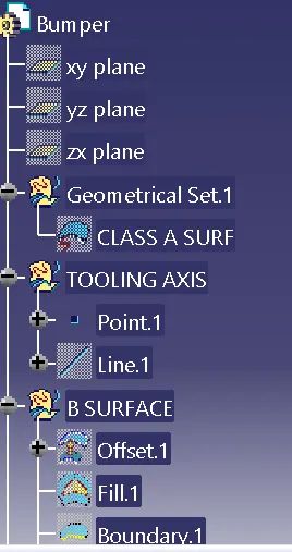
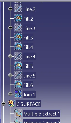
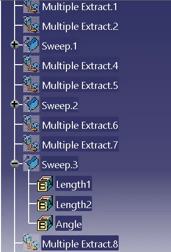
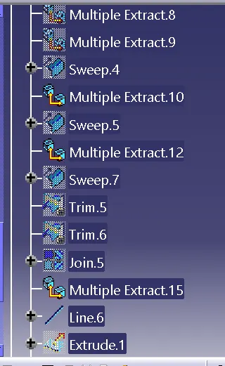
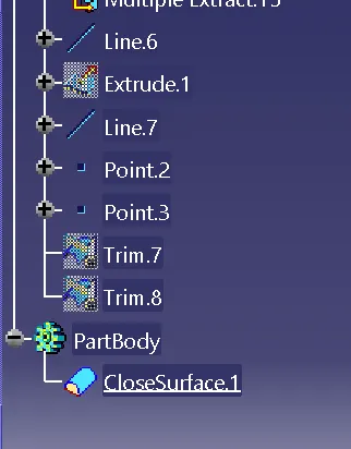
TREE SHOTS:
CONCLUSION:
To use class-A surface and create Tooling axis, Draft analysis were performed.
The solid component was created from the surface model.