Week 8 - Challenge 4 - Bumper
TOOLING AXIS
Here tooling axis is created normal to the flat surface at which we can see the whole surface. This is because the given surface is not symmetrical. That is simply extract that flat surface, create a midpoint on the surface, and create a normal line to the surface and pass-through this point. Bisecting line method for creating a tooling axis is suitable for symmetric surfaces.
DRAFT ANALYSIS
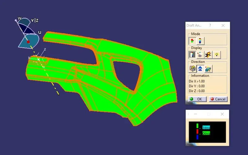
figure 1. class A surface draft analysis
- The draft analysis of the class A surface ensures that the class A surface is posses a proper draft angle based on the tooling axis.
- Draft is providing angles or tapers on product features such as walls, ribs, posts, and bosses that lie parallel to the direction of release from the mold easing part ejection.
- Using the draft analysis tool we can identify the zones using color codes and high lights the areas which deviate from the specified values along a defined draft direction.
- Here color code used is a green color indicating that the draft is 3 degrees or above, the red color indicated that the draft is 0 degrees and the blue color indicated that the draft is in a negative direction which is a minus value.
- from draft analysis of class A surfaces we can see that green color is all over the surface which means the surface is suitable for further process and it qualified for optimum draft angle.
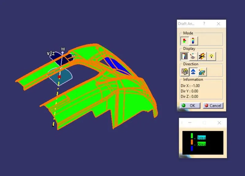
figure 2. Solid draft analysis
- Draft analysis of the solid model is similar to the way of draft analysis of surface A . check the solid part to whether it possesses the required draft. here we can see that on top it shows green which is a positive draft and on the bottom shows blue which is a negative draft. in the case of C surface, some portion which are along the draft direction shows green and other section which are bottom side shows blue colour. That is this solid model posses the ease of ejection from the mold. The color code is a green color indicating that the draft is 3 degrees or above, the red color indicated that the draft is 0 degrees and the blue color indicated that the draft is in a negative direction which is a minus value.
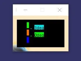
figure 3. colour code
- solid model with the proper color code of the draft angle in various orientations
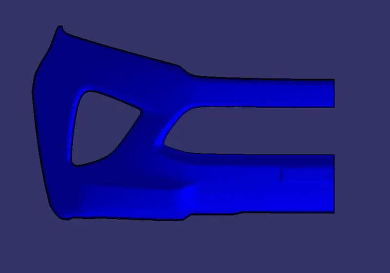
figure 4. front view
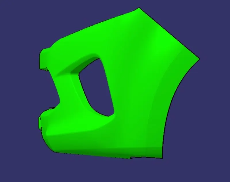
figure 5. left side view
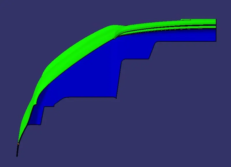
figure 6. top view