Week 8 - Challenge 4 - Bumper
AIM
To Create the Bumper Plastic component through the given Class-A surface.
THEORY
Bumper
A bumper is a structure attached to or integrated with the front and rear ends of a motor vehicle to absorb impact in a minor collision, ideally minimizing repair costs. In other words, A bumper is a bar attached transversely in front of or behind a car body to prevent contact between an obstruction and the car body or to cushion the shock of collision between vehicles.
Numerous developments, improvements in materials and technologies, as well as greater focus on functionality for protecting vehicle components and improving safety have changed bumpers over the years. Stiff metal bumpers appeared on automobiles as early as 1904 that had a mainly ornamental function.

Bumpers today are no longer made of steel and rubber, but of a plastic outer fascia over a lightweight, impact-absorbing polystyrene foam core.
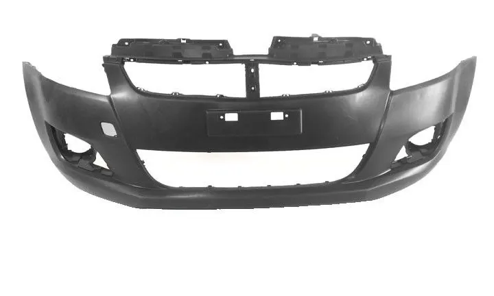
Bumpers ideally minimize height mismatches between vehicles and protect pedestrians from injury. Regulatory measures have been enacted to reduce vehicle repair costs and, more recently, impact on pedestrians. Bumpers today are designed to mitigate injuries to pedestrians and to minimize weight at the ends of the vehicle, thereby increasing occupant protection from progressive crumpling in a serious accident.
Tooling Axis
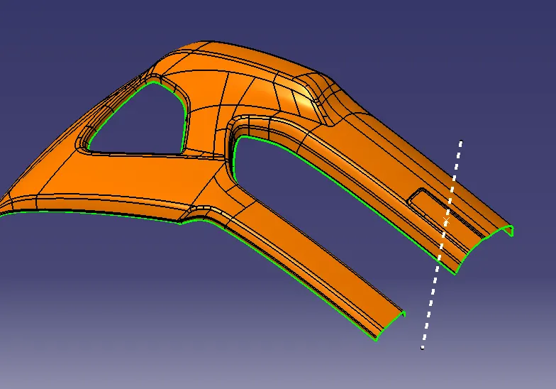
Tooling Axis is the direction in which the mold or core and cavity opens and closes. While designing a component first thing is to define the tooling axis.
Procedure
- Check the connectivity of given Class A Surface i.e no gaps between the surfaces.
- Analyse the component along x,y,z direction and check which is the best possible tooling direction (Here X)
- Create a point at flat surface by extracting it.
- Draw a line perpendicular to extracted flat surface through the point and that is the tooling axis.
Draft Analysis
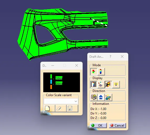
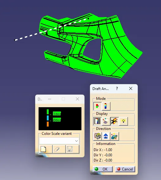
Draft analysis is used to analyze whether the part model created in CAD id manufacturable based on the draft condition applied.
Draft is required on all parts in the direction of mold movement in order to allow parts to release or eject from the mold properly. Most part or application require minimum `0.5^o - 1^o` as draft angle, however `3^o` is widely accepted as the norm.
Procedure
- First change the view to " Customize View Parameters" and select Material option.
- Select Feature Draft Analysis from the tool bar.
- Click on the direction, drag and drop the compass to the component such that it should coincide with the tooling axis.
- Lock the draft direction and click on the component.
- Green colour shows the positive draft, cyan as zero degree and red as negative draft
Class A Surface: Class A surface is any of a set of freeform surfaces of high efficiency and quality. In other words, Class A surface is the aesthetic surface.
Class B Surface: Class B surface is the thickened suface or engineering surface where all ribs etc will come.
Class C Surface: It is the Surface which joins Class A and Class B surfaces.
SOFTWARE USED
Catia V5
DESIGN
Thickness Given: 3mm
Tree Structure
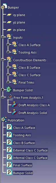
Tooling Axis
Draft Analysis
Class A Surface
Solid Component
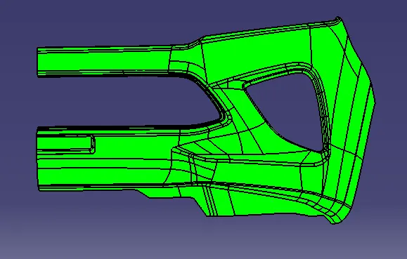
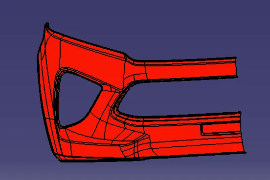
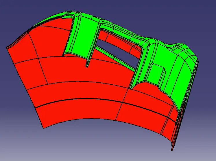
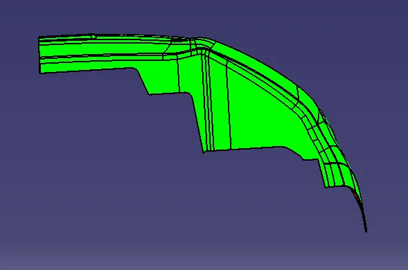
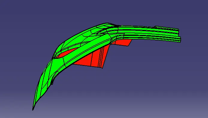
Class A Surface
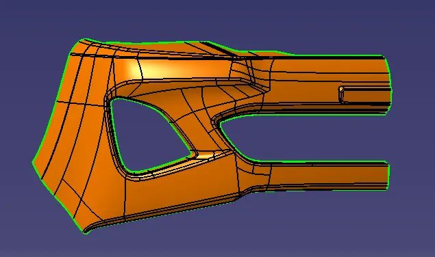
Class B Surface
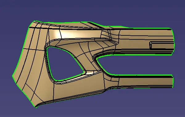
Class C Surface
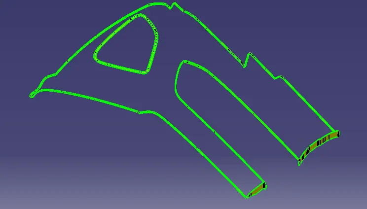
Final Joined Surface
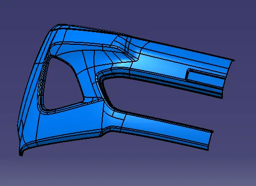
Final Solid
Isometric View
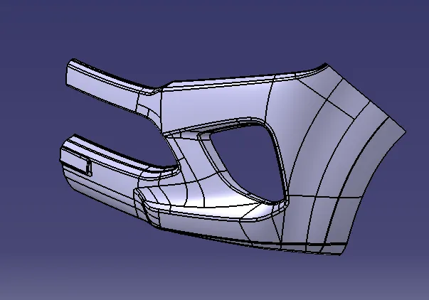
Front View
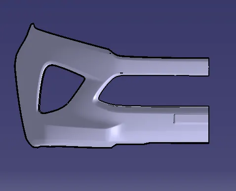
Back View
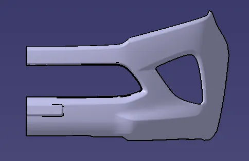
Left Side View
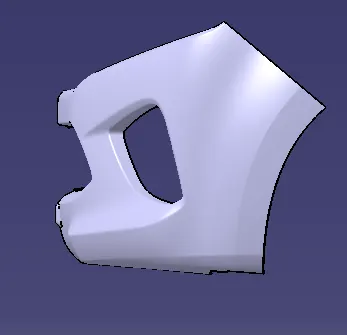
Right Side View
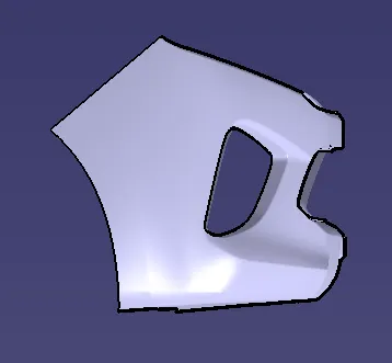
Top View
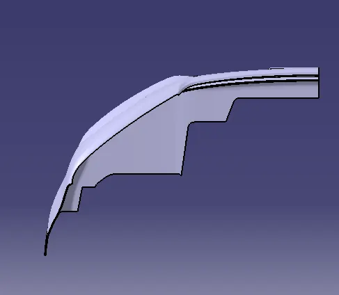
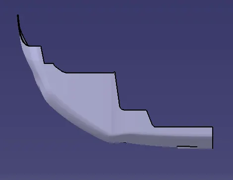
Bottom View
CONCLUSION
Bumper Plastic component through the given Class-A surface has been created in Catia