Week 8 Challenge
1)
AIM:
To apply the following loads for the already modelled structure from previous week.
- Form a Load case as DL for Dead Load
- Apply Self weight
- Apply member load of 3 kN/m on the rafter
- Apply member load of 6 kN/m on the secondary beams
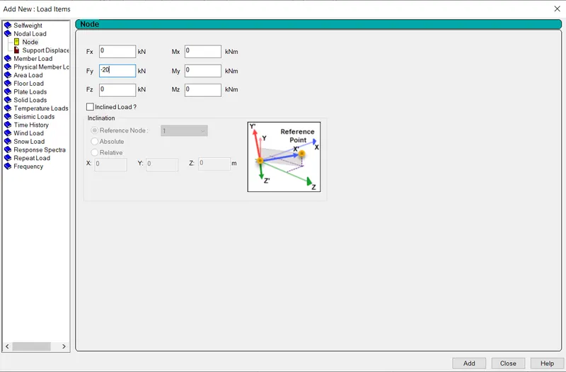
- Apply point load of 20 kN at node intersecting inclined member on the top chord.
- Form a Load case as LL for Live Load
- Apply member load of 4 kN/m on the rafter
- Apply member load of 7.5 kN/m on the secondary beams
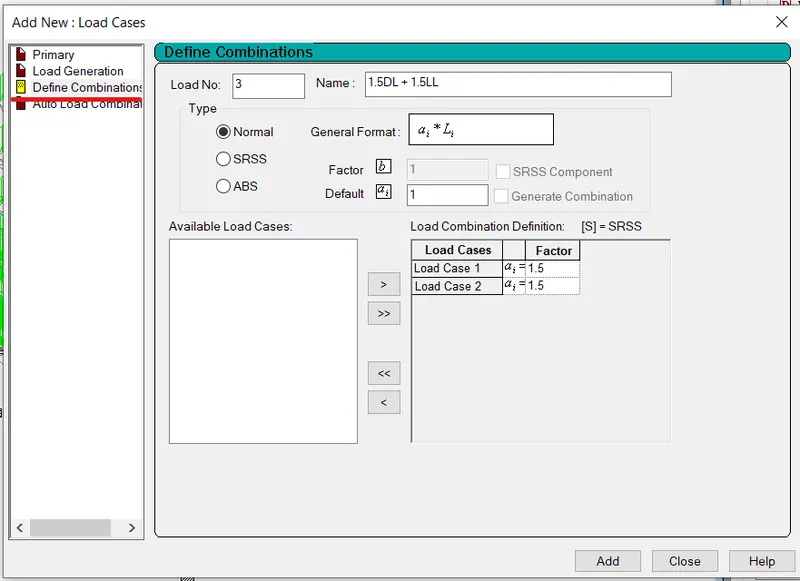
- Form load combination 1.5DL+1.5LL
PROCEDURE:
- Open the previous week STAAD file.
- Go to loading tab, and click on it and add loading case.
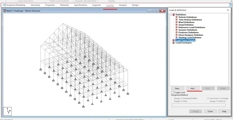
- Select the Load Type as Dead load and give the name as Dead Load and then assign the Self Weight for different Strucutral Elements under this load case.
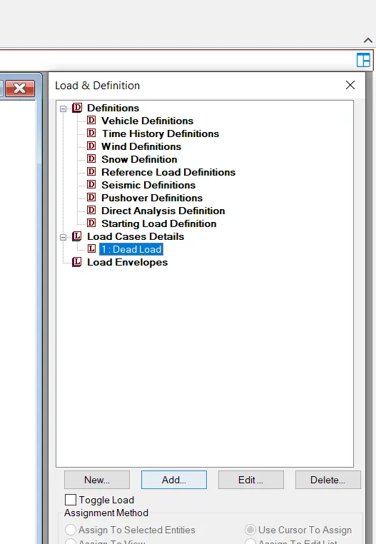
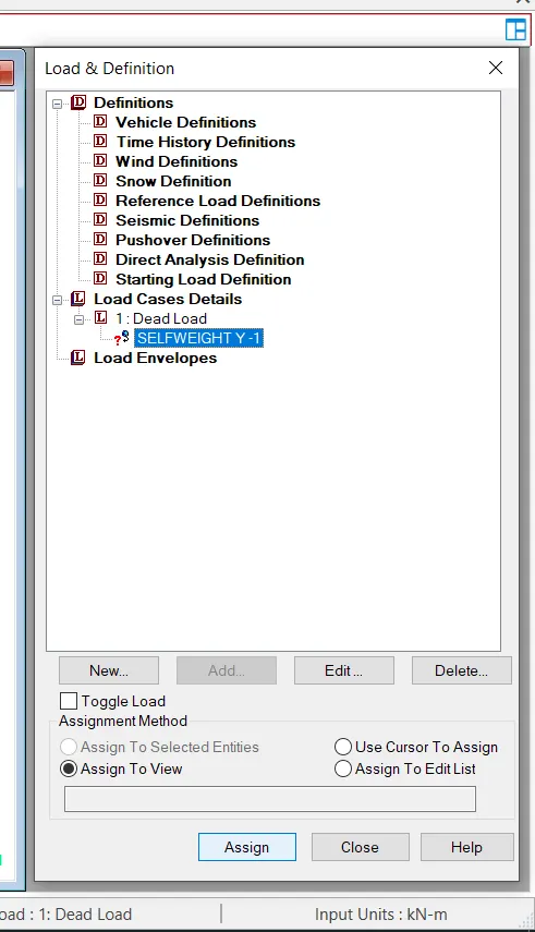
- Assign the Selfweight to all the structural elements.
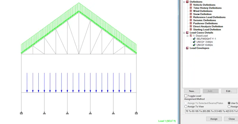
- Now, similarly under the Dead Load Case add 3kN/m Member load on Rafter.
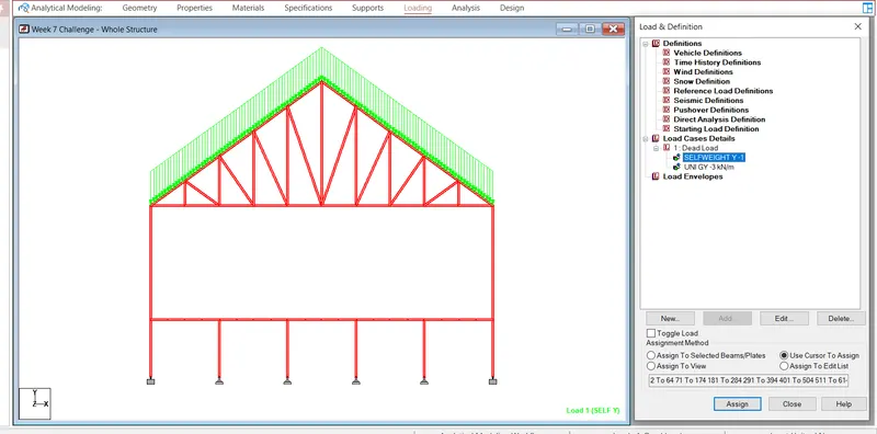
- Similarly add 6 kN/m member load on Secondary beam.
- Assign the nodal load of 20 kN on point of intersection of Rafter and inclined brace.
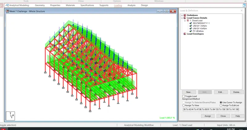
- So now overall dead Load has been assigned to the structure.
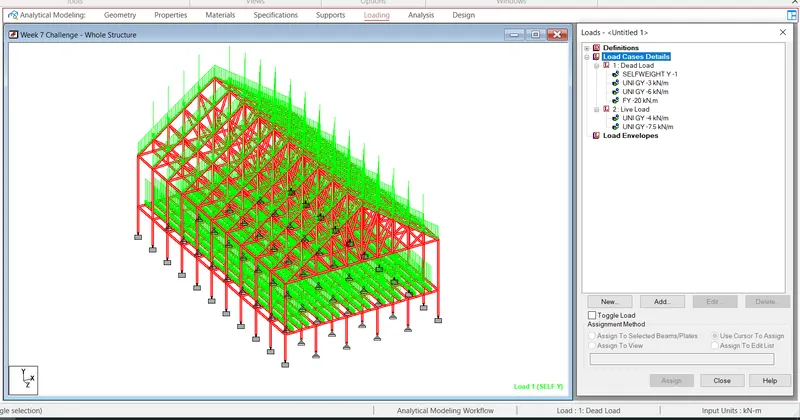
- Similarly create Live Load and apply the load as shown in below figure for the structure modelled.
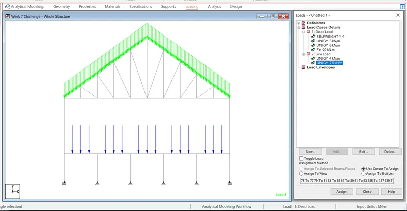
- Final Loading Diagram after applying both Dead Load and Live load will be as shown in figure.
- Then define a load combination of 1.5DL +1.5LL using define combination as shown in figure.
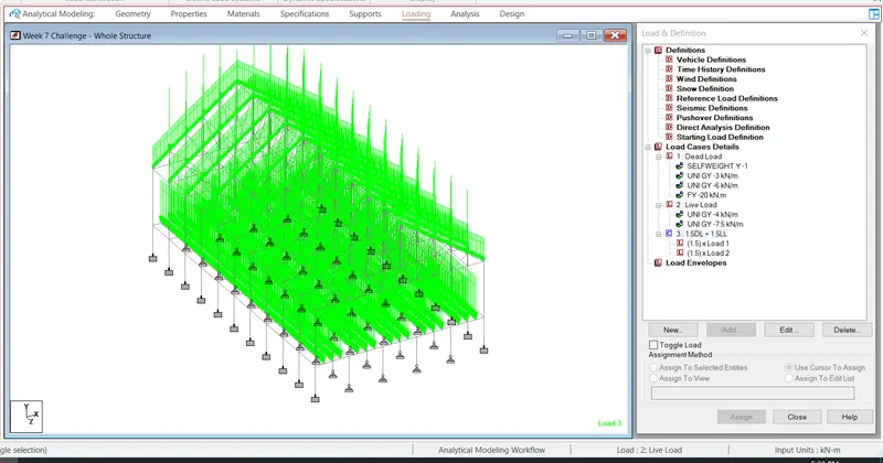
- Click on Add and the load combination has been added in Load Case details.
Result:
All the given loading cases Dead Load and Live Load has been added succesfully to the modelled structure.
2)
AIM:
To run the analysis and find following results on the member mentioned
- Run the analysis
- Find the Maximum Moment in the Secondary beam for 1.5DL+1.5LL case
- Find the Maximum Axial force on the inclined bracing and identify the member having the maximum force for 1.5DL+1.5LL case
- Identify Bottom chord of Truss having Maximum shear Force & Maximum moment for 1.5DL+1.5LL case and present the values.
Procedure:
- Open the staad file we have modelled in the above challenge.
- After loading cases are added, we have to run the analysis.
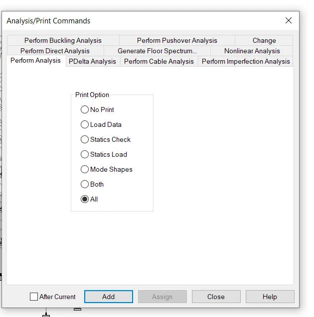
- So, go to Analysis tab, click on last load case and click on Define Commands.
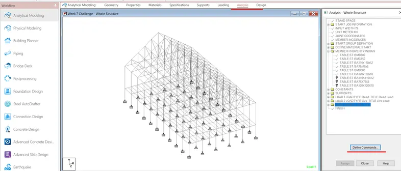
- Now, click on perform analysis
- Then click on all option and then click on Add.
 ----
----
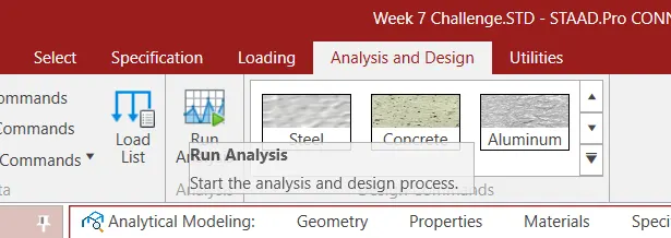
- Now, click on Run Analysis in analysis and design tab.
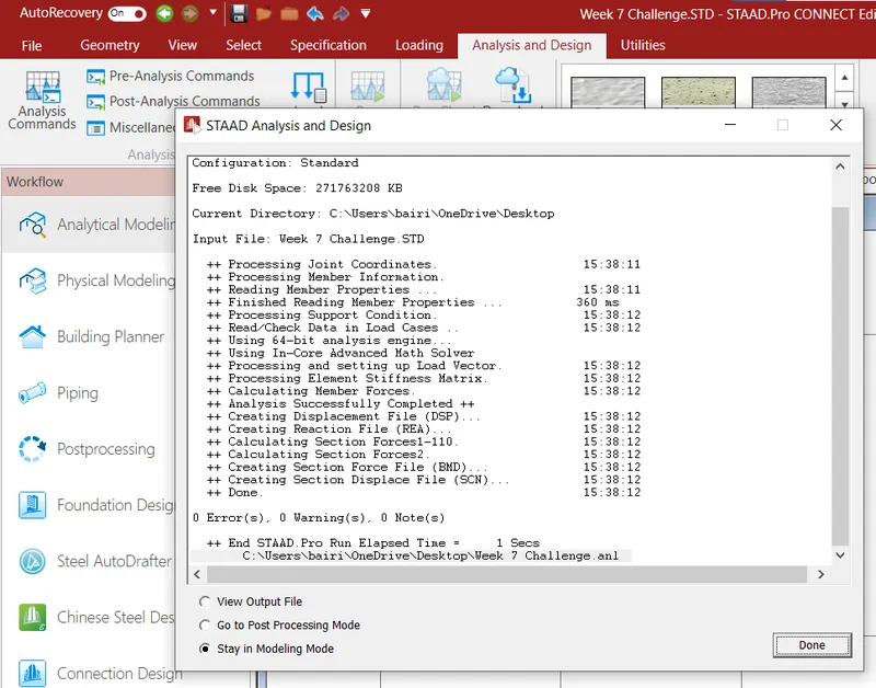
- The below window will pop up after the analysis is completed.
- Click on view output file to see the output results.
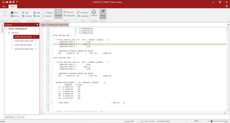
- Final Result of the analysis will be pop-up in different window as shown below
- Now, we will find the Maximum moment in the secondary beam for 1.5DL + 1.5LL load combination case.
- Go to Post Processing Option present on the Left Side. Go to View and select on Secondary beam to view.
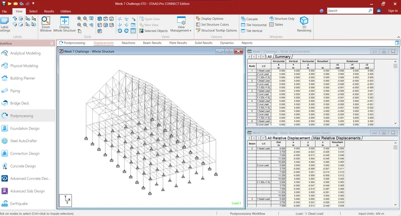
- After only selecting Secondary Beams, Go to Result Tab, and select `M_z` to view the Bending Moment Diagram.
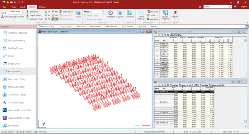
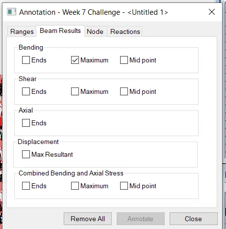
- `Go to annotate option and check the maximum to view the Maximum Bending Moment`
- Now, we get the maximum values of Bendig Moment as 54.268 kN-m.
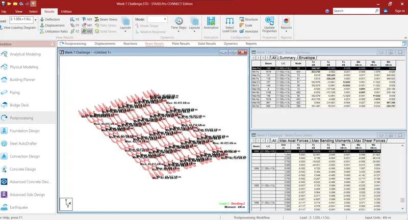
- Similarly, we will now find the maximum axial force on the inclined bracing for 1.5DL+1.5LL Case.
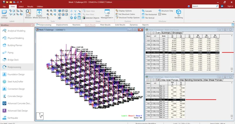
- Maximum Axial force we got as 153.934kN on Beam Number 1160 and 1161.
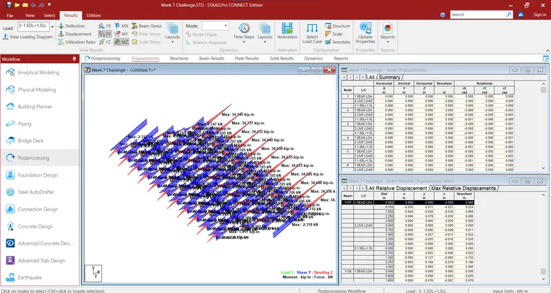
- Now, we can get the Maximum Shear Force and Maximum Bending Moment for the bottom chord of the Roof Truss as 2.40 kN and 3.925 kN-m.
Result:
These are the following results obtained after the analysis of the structure:
- Maximum Moment in the Secondary beam for 1.5DL+1.5LL case = 54.268 kN-m.
- Maximum Axial force on the inclined bracing and identify the member having the maximum force for 1.5DL+1.5LL case = 153.934 kN
- Maximum ShearForce and Maximum Bending Moment for the bottom chord of the Roof Truss as 2.40 kN & 3.925 kN-m.
3)
Aim:
To identify the Warnings and fix the same and run the analysis for the given STAAD File.
Procedure:
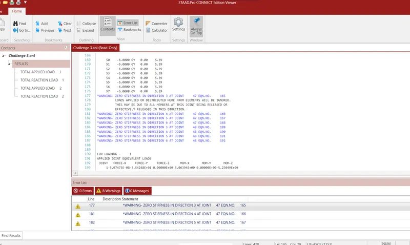
- After running the analysis for the above model 8 warning messages were displayed as shown in below figure.
-
Possible reason for error:
A joint exists where the only structural components connected at that node are truss members, there is no rotational stiffness at that node along any of the global degree of freedom
- Possible solution:
- Go to Node Speciification menu to create Master Node.
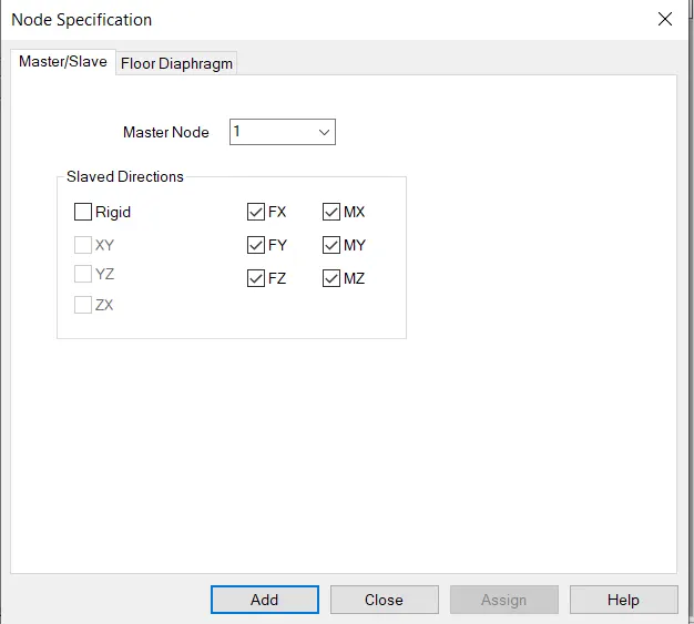
- Run the analysis again to see if there are any more warning messages left.
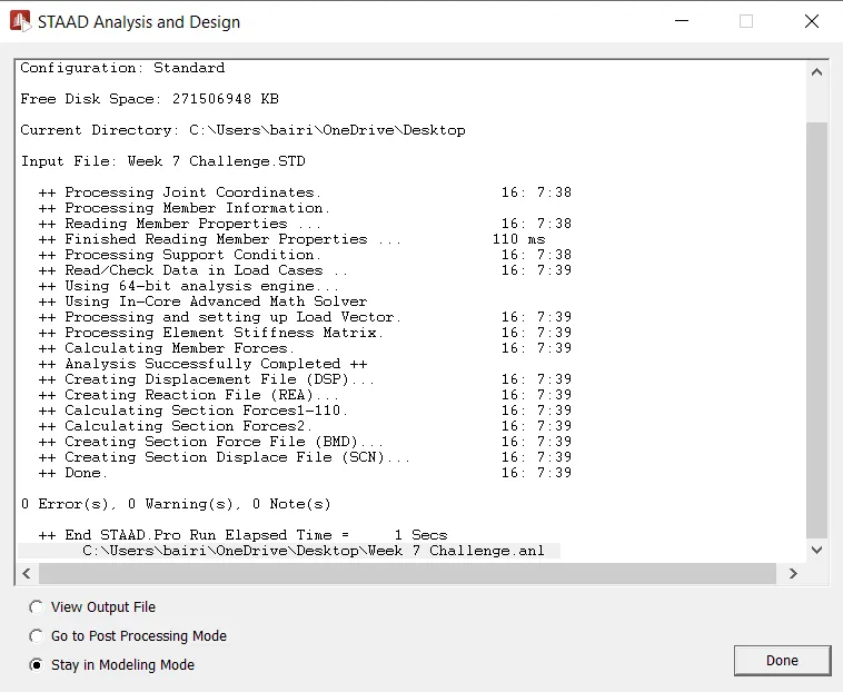
- We can see that there are zero warnings that means warnings has been resolved.
Result:
Analysis has been done and 8 warning messages which were seen in the above challenge are now resolved successfully and analysis report with 0 warning message has been obtained.
4)
Aim:
To apply Design parameters for structure modelled for code IS 800:2007.
- Effective Length Lx, Ly, Lz for beams, Truss elements
- Effective length factors Ky, Kz for Columns
- Apply other design parameters for respective members
Procedure:
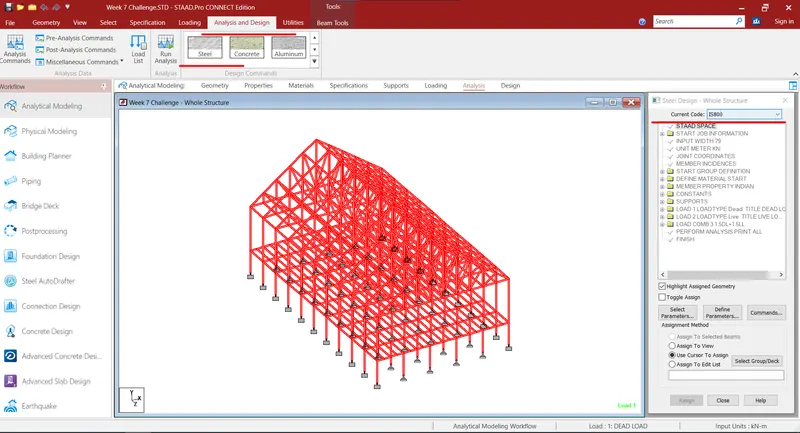
- Go to analysis and design tab, select all the structural members and assign steel as the basic material to them.
- Also select the IS 800 code as shown in below figure.
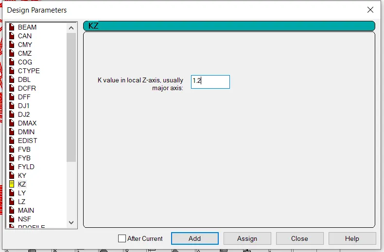
- Now, define the parameter `L_y,L_z` for beams and trusses and `K_y , K_z` for columns.
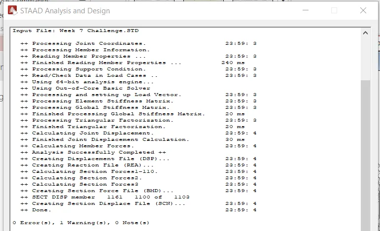
- Now, run the analysis again to see that there is no error.
- Other parameters have also been applied.
Result:
Design parameter has been successfully applied to the modelled structure in STAAD.Pro.