Week 8 - Challenge 3 - Switch Bezel Design
AIM:
To Create the Switch Bezel Plastic component through the given Class-A surface. To begin with, the tooling axis for the given Class-A Surface should be created meeting the requirements of the draft angle and at the end perform the Draft analysis on the model.
procedure for creating the tooling axis, class b and c surface:
- we get the input of class A surface for switch bezel in (igs) or catpart format to design.
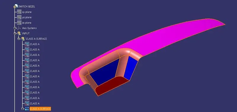
- After getting class A surface as input . the point is formed using the extraction of base from the switch bezel.
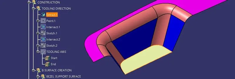
Base Extraction from switch bezel
- In point Definition dialog box , surface option is selected . In the surface of base extraction the vertical and horizontal value is given as zero.then point is formed at the midpoint of the surface.
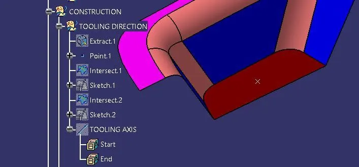
- Using intersection tool, we select the zy plane as first element and class a surface as second element. intersection tool will the the tooling direction which is intersection between the plane and class a surface.
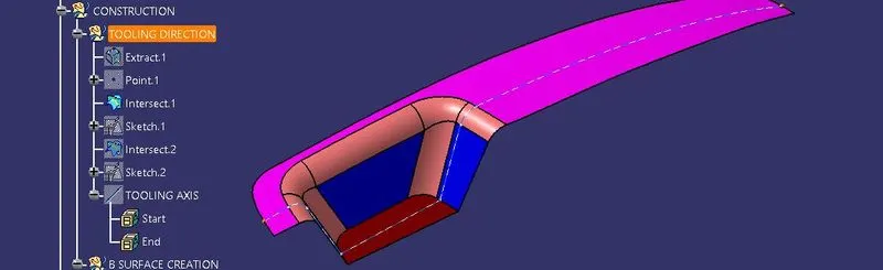
- Using intersection tool, we select the zx plane as first element and class a surface as second element. intersection tool will the the tooling direction which is intersection between the plane and class a surface.
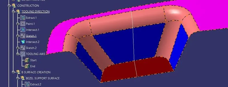
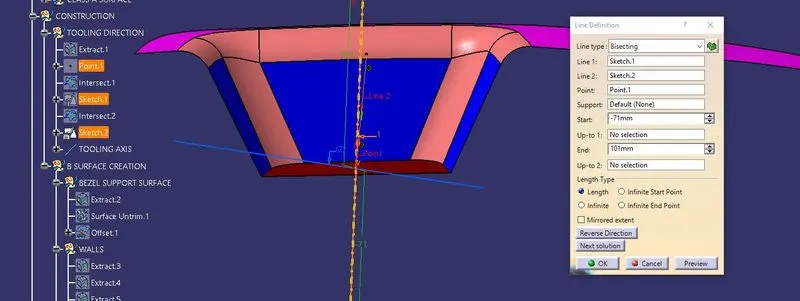
By Using the intersection 1, we created a sketch usings the walls of the switch bezel and created a dummy tooling axis along the zy plane by bisecting lines.
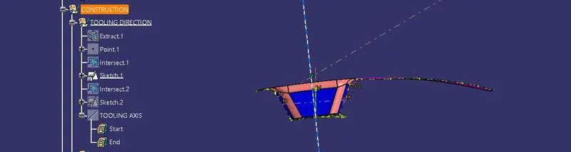
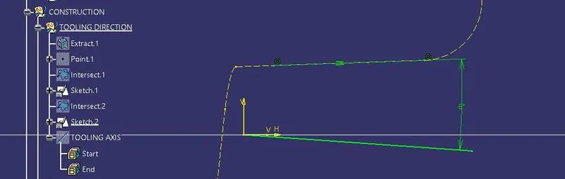
By using the intersection 2 , angle line is created to clear the drafting at the mid wall of the switch bezel.
from bisecting the two dummy tooling axis we get the tooling axis.
Now the B surface is created from the class a surface. b surface is created by the extracting the class a surface and giving them offset. the offset is then used for thickness of the switch bezel using class c surface.
- In B surface the extraction of bezel supporting surface is done and colour is given to it.

- untriming the extracted surface using surface untrim option.

- then, the extracted surface offset is given to the untrimed surface.
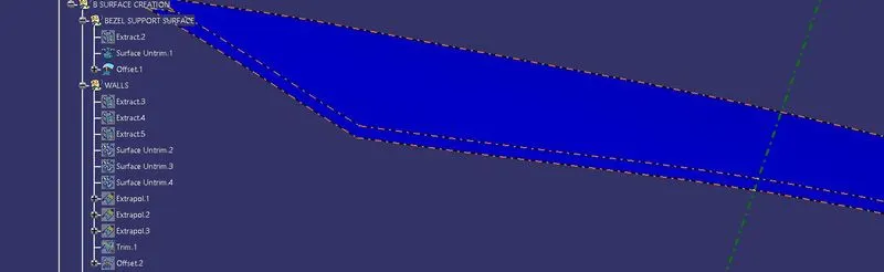
From Class A surface the bezel walls are extracted to form b surface walls.
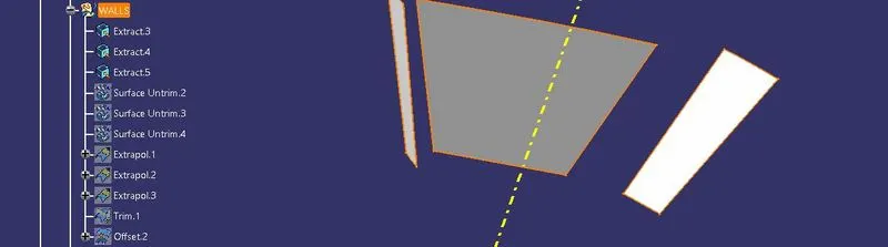
these are the extracted surface from the class a surface.
- then the extracted surface is untrimed using surface untrim option.
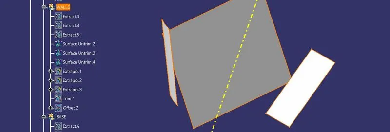
surface untrim option is done.
- untrimed surface are extrapolated from the b surface walls.
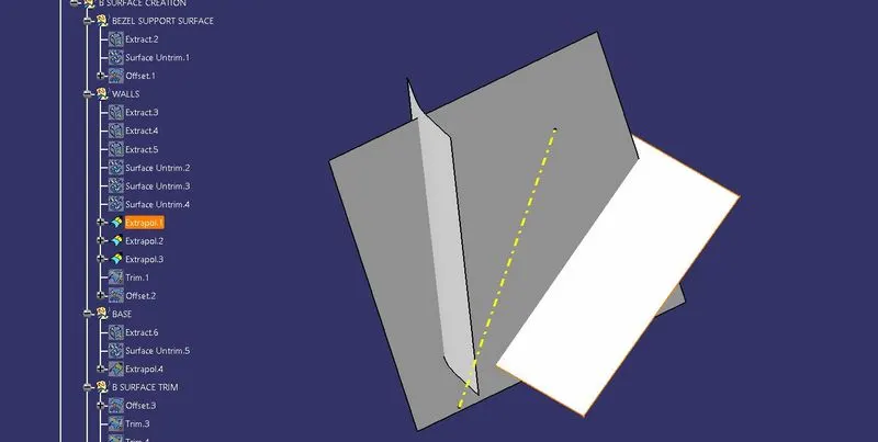
this is the extrapolated surface from the surface untrim option.
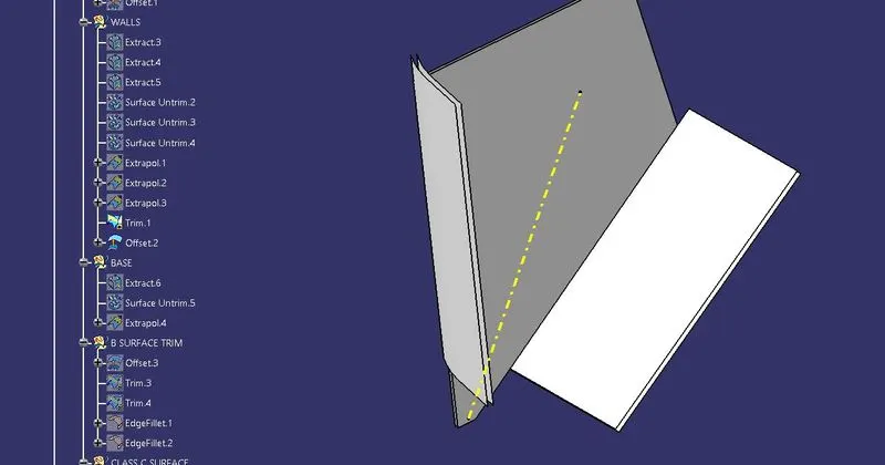
- Now the extrapolated surface is trimed with trim operation which is denoted as trim 1
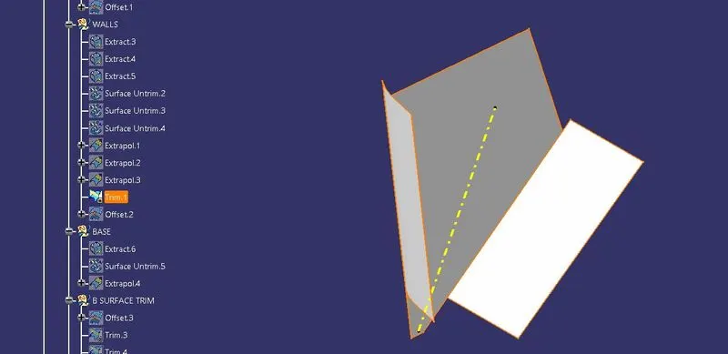
then, for creating the class b surface the trimed surface is extracted and offseted from the A surface.
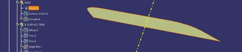
- Now the base surface from the class a surface is extracted from the bezel,for joining the walls and base of the bezel.
the extracted base surface from the switch bezel is untrimed by using surface untrim option.
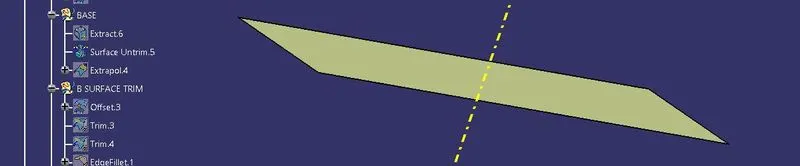
the untrimed surface is extrapolated from the base of the bezel.
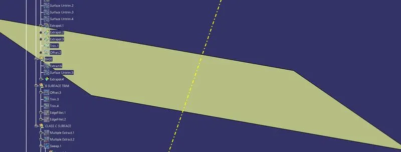
Now the extrapolated surface from the A surface is offseted . the offset from the extrapolated surface is called b surface trim.
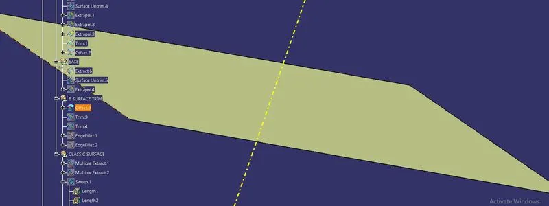
In B surface trim the walls , bezel supporting surface and base are trimmed to form the b surface and fillets are given to the b surface trim.

this is the triming operation without base surface.
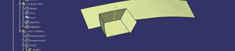
this is trim operation with base surface.
after triming the fillets are given to the b surface trim.
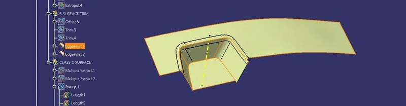
fillets are the created as b surface .
Now , creation of Class c surface.
for creating the c surface the multiple extract option is selected for giving boundaries to the switch bezel.
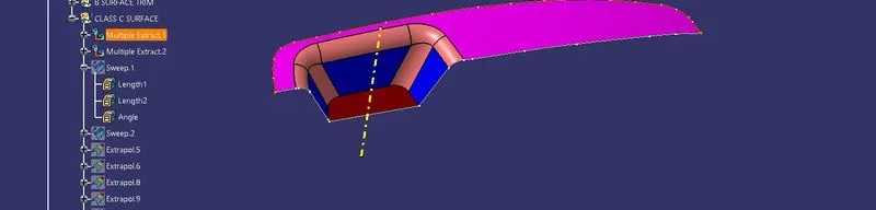
their is two multiple extract which is multiple extract 1 and 2 which are created at the boundaries of the switch bezel.
the first sweep is called sweep 1 which is the sweeped material from the multiple extract 1 boundries.
the second sweep is called sweep 2 which is the sweeped material from the the multiple extract 2 boundries.the sweeped portion for the boundries are not smooth they has point which does not giving clear body to the sweeped materials.then the multiple extract are replaced with curve smooth lines these line give smooth finish to the material and provides a clear class C surface.
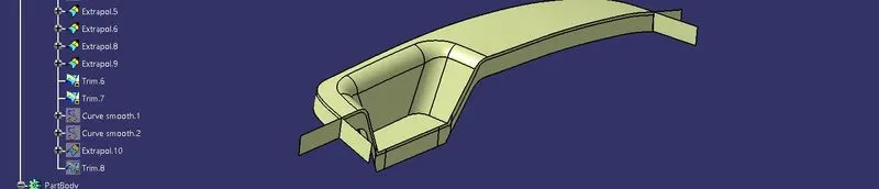
we have given the sweep using the curve smooth and tooling axis with draft angle of 3 deg which is recommend from the industry. In sweep option is used with drafting angle reference option in sweep dialog box.
the sweeped surface is then extrapolated and trimed to finish the smooth class C surface.
then, the process is continued for creating the class C surface From Class A and B surface .from the class C surface and Class B surface total body is trimmed and formed the class a surface on top ,class b surface at bottom and hollow space which is class c surface.
then surface body of the switch bezel is created.
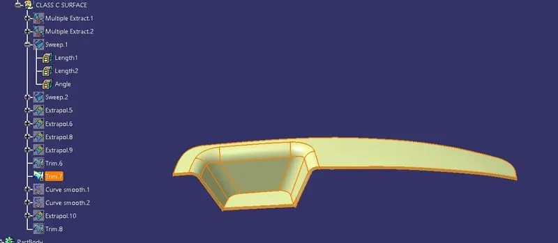
By using the part body close surface option. we converted the surface body into part body.

After creating the part body using close surface the draft analysis is done.
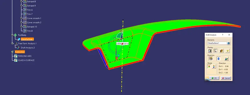
the drafting feature is present in insert option. after applying the draft angles with tooling axis in mode option.click on the body to check the drafting colours
- green which is above 3 deg
- red which is 0 deg
- blue which is below 0 deg.
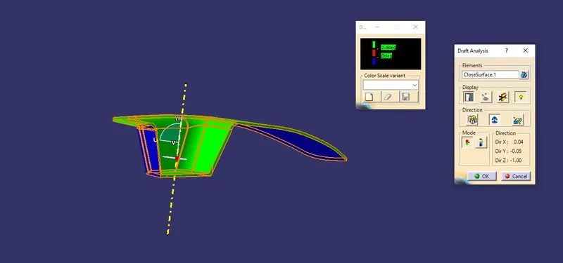
before the drafting installation process the compass direction is locked using compass option present in it.
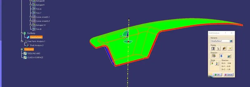
this determine the direction of the tooling axis is acted along the drafting angle for the maunfacturing and clearing the material for manufacturing.
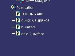
Last step is to publish the tooling axis and class a surface and b surface and c surface.
conculsion:
the switch bezel drafting analysis is done with creating tooling axis with tooling direction