Radar Mast & Final Assembly of Yacht
AIM:
1. Radar Mast
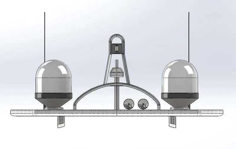
Front plane:
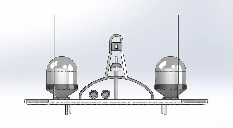
Back plane:
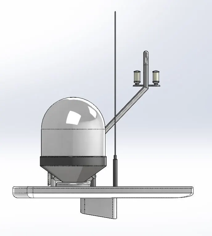
Mid Plane:
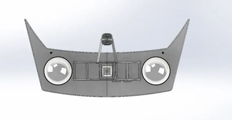
Top plane:
Bottom Plane:
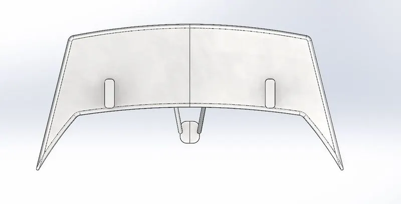
Isometric view:
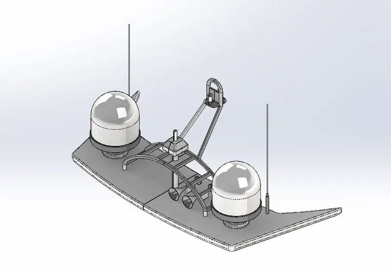
Trimetric view:
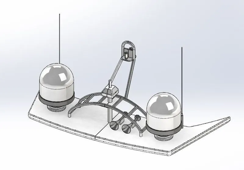
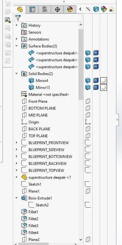
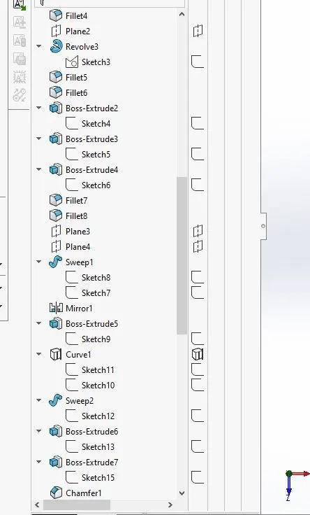
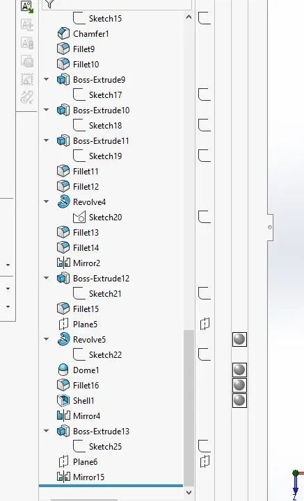
Feature Tree:
2. Yacht Assembly
TITLE OF THE PROJECT:Assembling and photo Realistic Rendering of yacht Model.
SOFTWARE USED: 1. Solidworks 2.solidworks visualize
OBJECTIVE:
- Designing of yacht parts with proper dimension.
- Assembling of the yacht model.
- Rendering of the Assembled Model of the yacht.
INTRODUCTION:
SolidWorks is a Solid Modelling Computer Aided design (CAD) and Computer Aided Engineering (CAE) computer program published by Dassault systems, that runs primarily on Microsoft Windows.The software is used for planning, visual ideation, modeling, feasibility assessment, prototyping, and project management.
The software is used for design and building of mechanical, electrical, and software elements.
DESIGN METHODOLOGY:
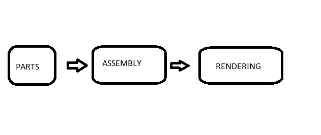
PARTS:
Parts is the default option available in solidworks for designing the models with proper dimension. parts windows consists of tools like features,sketch,surface and other tools like rendering (photoview 360),etc...
ASSEMBLY:
Assembly is another window like parts but its consists of toolbars like render tool,assembly,layout,sketch and layout. Assembly windows contain mates which are coincidents,parallel,perpendicular,tangent,concentric and lock,distance,angle.
Assembly Mates are catagories as standard mates,advanced mates and mechanical mates.
Mates which are used in this software:
- STANDARD MATES:
- Coincident :
Positions selected planes, edges, and faces on the same infinite plane. If two vertices are chosen then will position them so that they touch.
- Parallel :
Keeps selected items at a constant distance from each other.
- Perpendicular:
Places selected items at a 90 degree angle from each other.
- Tangent:
Places a cylindrical, spherical, or conical face tangent with another component.
- Concentric:
Places two cylindrical, spherical or conical faces of a part so that they share the same centerline.
- Lock:
Keeps two components at the same position and orientation.
- Distance:
Specify a distance between two components planes, faces or edges.
- Angle:
Place components at a desired angle from another component. Can select an edge, face, or plane
- ADVANCE MATES:
- Width:
Centers a tab reference, a parallel planar face, a drafted face, or cylindrical face, within the width of a groove.
- Distance:
Add a limiting distance between components by giving it a maximum and minimum distance between components faces, edges, or planes.
- Angle:
Adds a limiting angle between component faces, edges, or planes by specifying a minimum and maximum angle.
RENDERING :
Rendering or image synthesis is the process of generating a photorealistic or non-photorealistic image from a 2D or 3D model by means of a computer program. The resulting image is referred to as the render.
photoview 360 is the tool which is used for rendering the images. It is a visualization and rendering solution included with Solidworks Professional and Solidworks Premium. Providing a highly interactive environment for viewing designs as well as for creating photo-realistic renderings that can be used to showcase your designs.
DESCRIPTION :
parts window contains tools like features, sketch, surface and render tools,etc..
sketch toolbar contains of tools like line,fillet,circle,smarts dimension and others.the tools which are used in the model are described below.
selecting the plane is the important step in designing.
- sketch:
Opens a sketch on a selected plane or surface. To open, left click on the icon and pick the desired plane or surface. To exit a sketch left click again on the icon or hit the exit sketch icon or hit esc. To cancel anyprogress on the sketch press the cancel icon in the upper right corner of the design space.
- smart dimension :
Creates a dimension for a selected sketch entity.
- Line :
Sketch a horizontal, vertical, or angled line.The centerline tool can be accessed through the drop down arrow and performs the same way.Double click to end the line and Also start a line by holding the left mouse button and end the line by releasing the button.
- corner Rectangle:
Sketch a rectangle or square. Each rectangle tool shows the user inputs in the tool by denoting the mouse “clicking” points as small red circles.
- polygon :
Sketched a polygon. Allows the user to input the number of sides on the polygon. Inserts pre-defined reference geometry to minimize sketch dimensions.
- perimeter circle:
Sketches a circle by using three points specified by the user. Can define the circle by two points instead of three by checking the circle icon under circle type in the property manager.
- Tangent arc:
An incomplete circle defined by its tangency to the sketch entity. Specify the tangent arc by left clicking a sketch endpoint and then left click to specify the endpoint of the arc.
- Sketch Fillet:
A tangent arc inbetween two sketch entities. Specify the radius by left clicking in the radius text box in the property manager
- Spline:
A two or three dimensional curve defined by a set of control points. Points within a spline can be added or deleted by left clicking on the spline point and saying delete or add spline point.
- Ellipse:
Sketches a complete ellipse. Left click in the design space to place the center of the ellipse.Next, define the major and minor axis by left clicking and then dragging the cursor to the desired position.
- Trim Entities:
Trim sketch entities to the desired shape. To trim a section left click on the desired sketch entity to cut away. Several trim options include power trim, corner, trim away inside, trim away outside, and trim to closest.
- Convert Entities:
Project a sketch entity, face, edge, curve, or contour onto the open sketch plane. To convert entities left click on the desired sketch, face, edge, contour, or curve and then left click on convert entities. A new sketch will be created on the plane fully defined using the geometry of the selected entity.
- Offset Entities:
Copy a sketch entity to a specified distance from the original entity. Must have a sketch entity already drawn and selected to use this tool. Select the offset distance in the property manager by left clicking in the offset distance text box and specifying the value.
- Mirror Entities :
Create a reflected copy of a desired entity about a centerline or axis. Make sure the entities to mirror box is highlighted in the property manager. Select the desired entities to mirror, or replicate by left clicking on each. Select the mirror about box in the property
manager by left clicking in the text box.
- Feature:
Features are the individual shapes that, when combined, make up the part. You can also add some types of features to assemblies. Features include multibody part capability. You can include separate extrude, revolve, loft, or sweep features, within the same part document
- Extruded Boss/Base
An Extruded Boss/Base feature will allow you to take a 2D sketch and add thickness to it in the third dimension and it is one of the oldest command in the solidworks
- Revolved Boss/Base:
Revolves add or remove material by revolving one or more profiles around a centerline and This feature is used to revolve a 2D sketch along an Axis
- swept Boss/Base:
Swept boss/base is one of the useful features which help to sweeps a closed profile through an open or closed path.that means ,when u have closed profile and you have a open or closed path.you can just sweep the profile that you have created to get the desired part.
- lofted Boss/base:
The loft feature creates a shape by making transitions between multiple profiles and guide curves.This tool is very valuable for modeling complex surfaces.
- Extruded cut:
The Cut-Extrude feature will then project the desired shape of cut based on the selected sketch and The Extruded cut operation allows you to easily remove material from a solid by extruding a profile along the normal to its plane.
- Revolved cut:
Revolved cut feature is one of the very useful solidworks feature tool, which helps to remove materials from 3D models possess axis symmetry. Revolved cut removes materials by revolving a closed profile a along an axis.
- Fillets:
Fillet/Round creates a rounded internal or external face on the part. You can fillet all edges of a face, selected sets of faces, selected edges, or edge loops
- Chamfer:
The chamfer tool creates a beveled feature on selected edges, faces, or a vertex. Set the Distance and Angle in the Chamfer PropertyManager or in the graphics area.A manipulator arrow appears that points in the direction in which the distance is measured.
- Linear Pattern:
linear patterns to create multiple instances of one or more features that you can space uniformly along one or two linear paths.
- Plane :
You can create planes in part or assembly documents. You can use planes to sketch, to create a section view of a model.
- Project curve:
It is a tool you are going to use to form 3D curves from two 2D curves from two different planes.
- Mirror:
Creates a copy of a feature, (or multiple features), mirrored about a face or a plane. You can select the feature or you can select the faces that comprise the feature. Select a body in a single model or multibody part to create a mirror entity.
- Surfaces:
Surfaces are a type of geometry that can be used to create solid features. Surface tools are available on the Surfaces toolbar. You cause surfaces in the following ways: Select surface edges and vertices to use as a sweep guide curve and path. Create a solid or cut feature by thickening a surface.
- Extruded Surface:
You can create extruded surfaces from models that include 2D or 3D faces and knit the extruded surfaces to surrounding features.
- Revolved surface:
A surface of revolution is a surface in Euclidean space created by rotating a curve around an axis of rotation.
- Sweep Surfaces :
These are surfaces that are generated from a section curve positioned along a path. Various Sweep types are available to extend the sweep definition as follows:
- Sweep by Two Guide Curves.
- Bounded Sweep
- Fixed Sweep
- Parallel Sweep
Parallel Sweep is defined as a section curve moving along a guide path while maintaining the section curve to be parallel to the guide path
- Lofted Surfaces:
- Ruled Surfaces:
- Trim surfaces:
- you can use a surface, plane, or sketch as a trim tool to trim intersecting surfaces
- You can also use a surface in conjunction with additional surfaces, as mutual trim tools
- In the PropertyManager, under Trim Type, select a type:
- Standard. Trims surfaces using surfaces, sketch entities, curves, planes, and so on.Mutual.
- Trims multiples surfaces using the surfaces themselves.
- Extend surfaces:
- You can extend a surface by selecting an edge, multiple edges, or a face
- Under Edges/Faces to Extend, select one or more edges or faces in the graphics area for Selected Face/Edges.
For edges, the surface extends along the plane of the edge
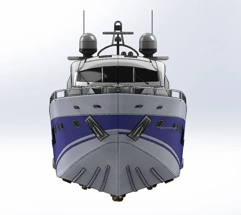
Screenshot of Assembly:
FRONT PLANE:
TOP PLANE:
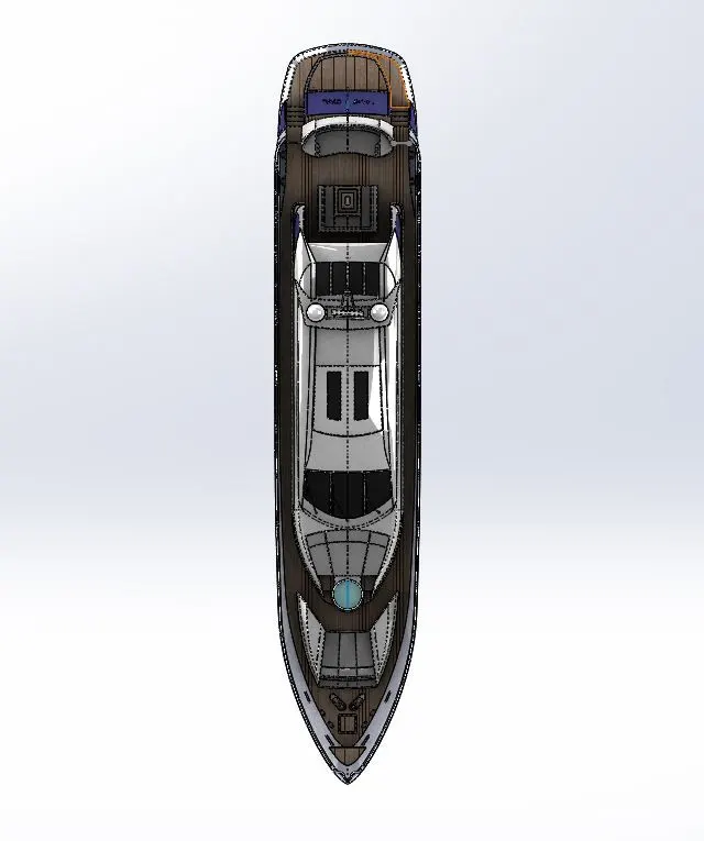
RIGHT PLANE:
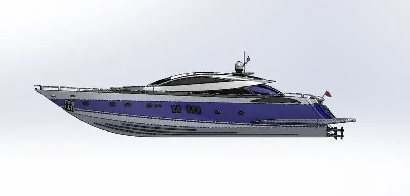
ISOMETRIC:
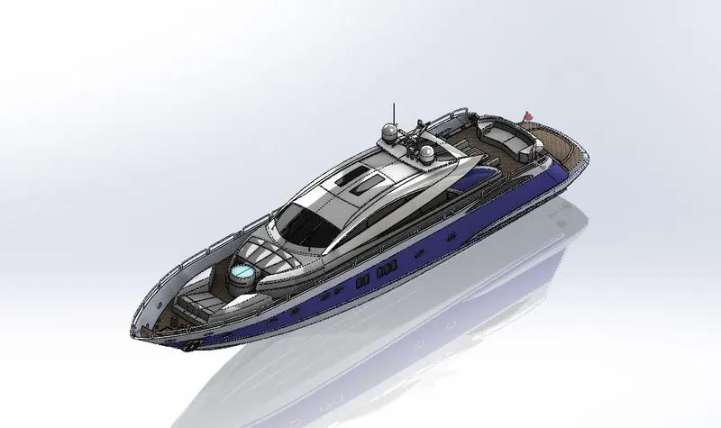
TRIMETRIC:
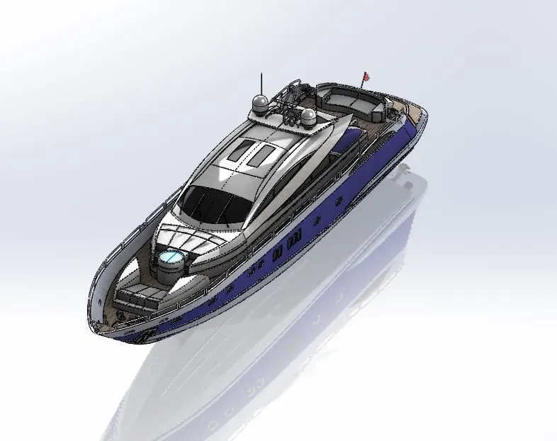
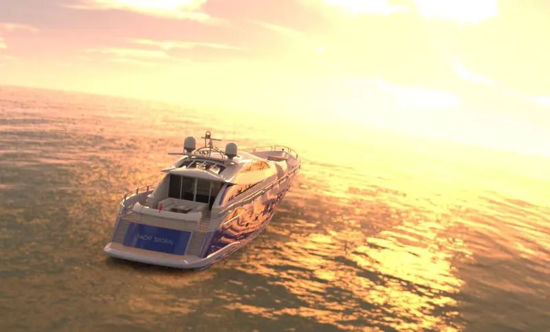
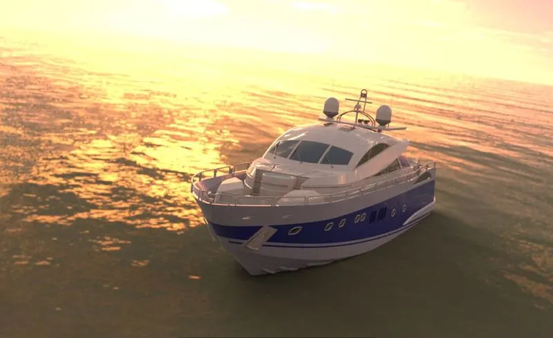
Rendering Images:




CONCLUSION:
Designing and assemblying of yacht is successfully executed and verified.