Week 8 - Challenge 3 - Switch Bezel Design
DRAFT ANALYSIS OF SWITCH BEZEL
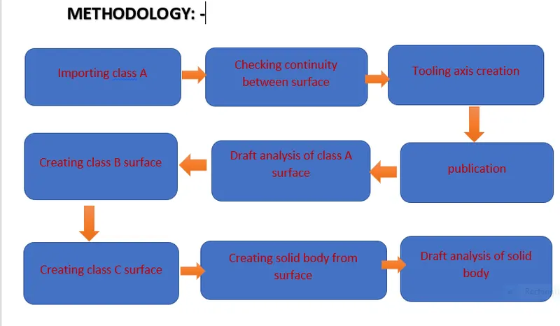
AIM: - To Create the Switch Bexel plastic component through the given class A surface. To begin with the tooling axis for the given class A surface should be created meeting the required of the draft angle and also create the class B surface and C surface.
INTRODUCTION: - Draft analysis is based on the color range identifying zones on the analyzes element where the deviation of the draft direction at any point of the corresponding specified values. Draft is required on all parts of mold movement in order to allow parts to release or eject from the property.
Draft is the angle in which the part is tapered to allow it to release. At the part cools it tends to want to shrink to the core side of the mold. The draft is allowing the part to release or eject without creating any friction between the surface of component and core and cavity plates.
Minimum draft angle is required 3degree (draft angle is 0.5 is given ideally to the features inside the plastic part) Draft angle vary 1 to 5 degree but 3-degree draft angle widely accepted. But for automotive sheet metal part the draft angle 7degree or more. Minimum possible draft angle is given for ribs screw holes, stiffener due to critical nature.
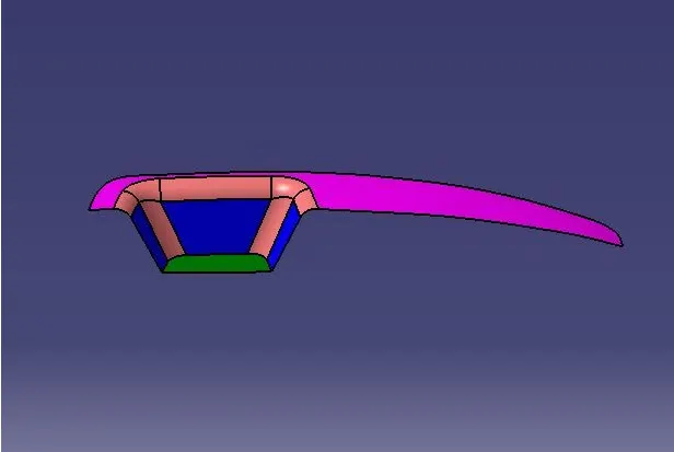
GIVEN CLASS A SURFACE
CLASS A SURFACE: -
In Automotive design a class A surface is any set of freeform surfaces of high efficiency and quality. Class A surface is done using computer aided industrial design application. Class A surface modelers are also called ‘’DIGITAL SCULPTORS’’ in the industry. Industrial designer develops their design stylish through the class A surface.
PROCEDURE
First check the continuity of the class A surface with the help of join or boundary command.

TOOLING AXIS: -
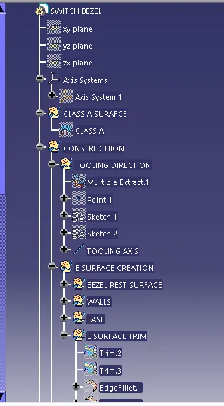
- Extract the base of the switch bezel using multiple extract command. create a point using point on surface option.
- Insert Axis system at that point and create the positioned sketch YZ plane
- Make intersection on it draw two inclined lines on the intersection.
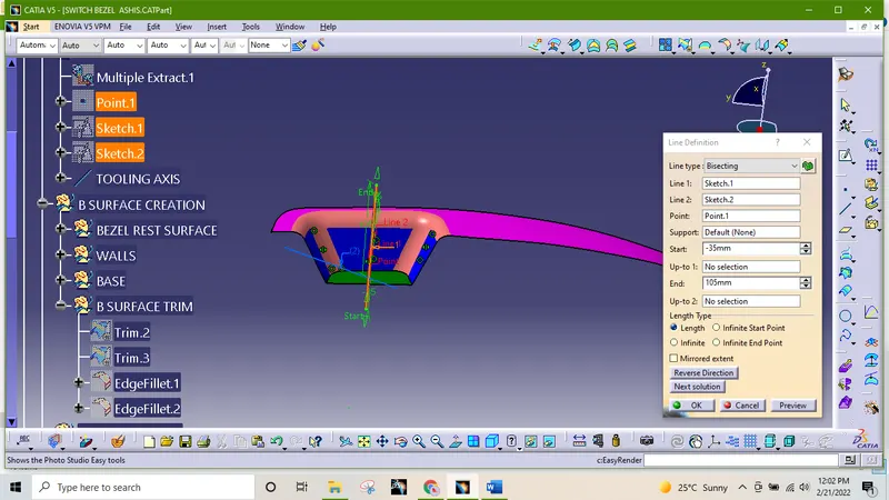
- Using the bisecting line option by selecting the two line and help of the point create the line which is tooling axis Y
- By using same procedure create a sketch on ZX plane make intersection on it. Draw line on the intersection and draw another line which is 3-6 degree from the first line which is tooling axis X.
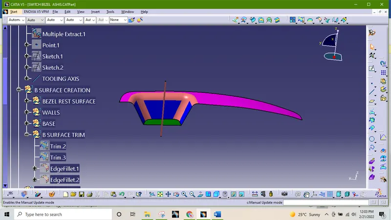
- Create a bisecting line using X &Y Tooling axis we get the tooling axis and publish it.
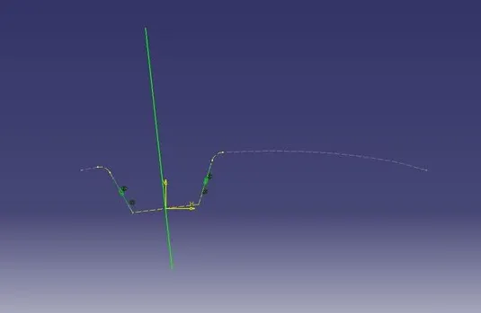
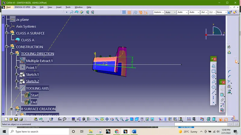
TOOLING AXIS
CLASS B SURFACE CREATION: -
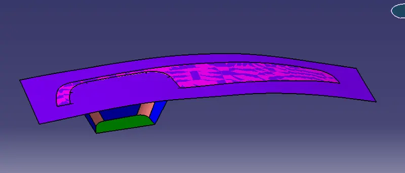
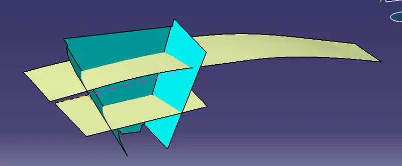
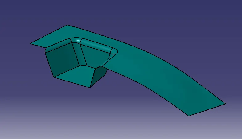
- Create the class B surface one by one first the Bezel Rest surface extract the surface, unitrim the surface repeats the operation for walls and base surface.
- For base and Walls offset for 2.5 mm which is the thickness of the component.
- Trim all the surface to form the class B surface.
- Now perform the fillet operation.
CLASS B SURFACE
CLASS C SURFACE: -
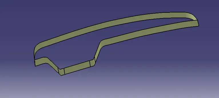
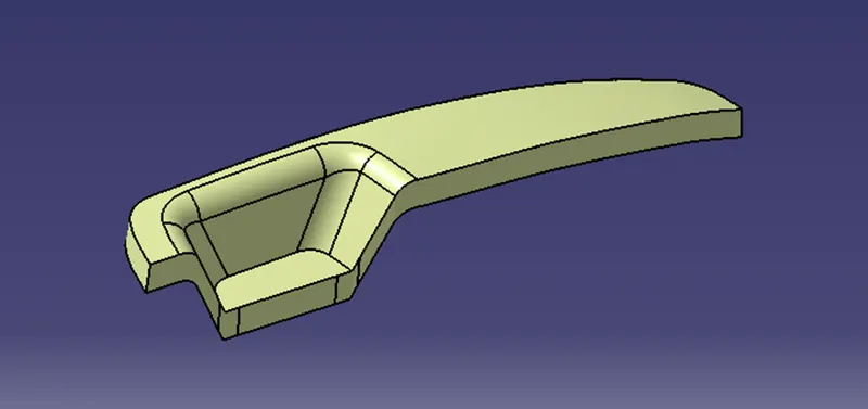
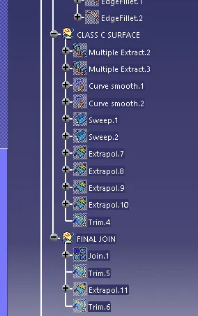
- The edges of the class A surface are extracted using the multiple extract and then converted into smooth curvature to avoid the patches.
- Sweep (with draft direction) option is used selecting the smooth curves as the guide curve and tooling axis as the direction and draft angle is 3 degrees.
- Trim the sweep that created and join it with the class A surface.
- Then trim the class C surface with class B surface.
CLASS C SURFACE
SOLID BODY CREATION: -
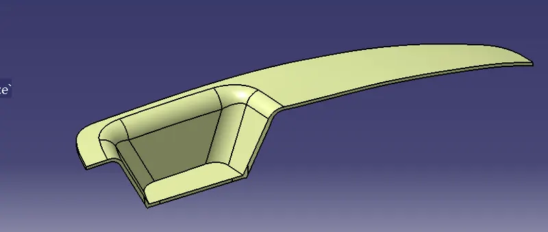
- Before creating solid body check the surface whether it is closed or have any gap in it.
- If there any gap then it can be joined using extrapolation and trim option.
- Design the part body and use close surface to make it solid body.
FINAL SOLID BODY
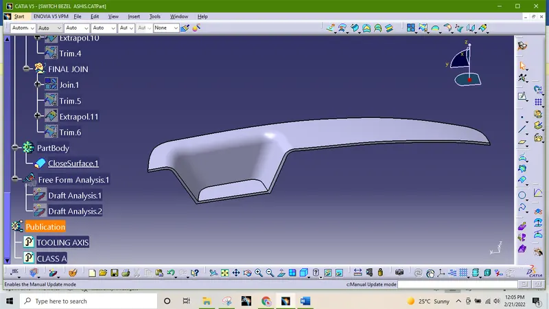
DRAFT ANALYSIS: -
- Final plastic parts are the nominal draft angle is 3 degrees but even 7degree is allowed for the subassemblies like ribs and slots.
- Insert< Analysis< Feature draft analysis
- First the compass is moved to the part which used to define the tooling axis new current draft direction then lock the draft direction using the lock icon.
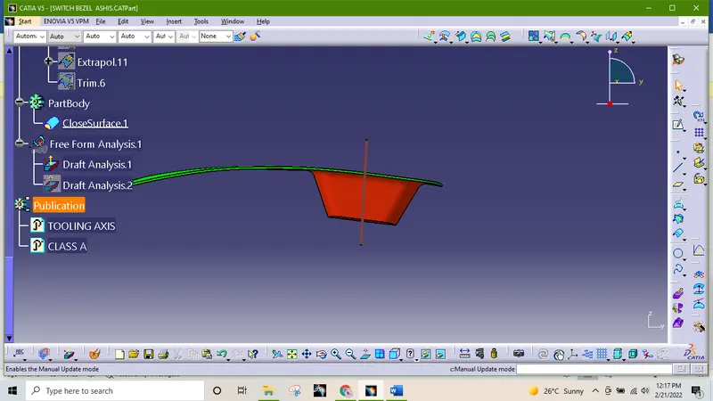
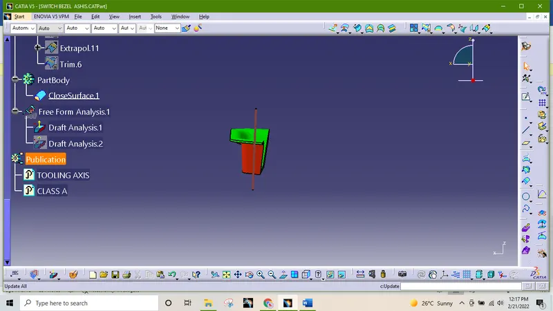
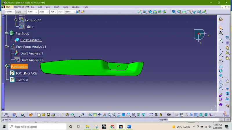
- The color of the chart indicates the draft if the color is indicated that means the part passes and used for further operation.
- By using the analysis under the running point icon, we can check draft angle at the various surface of the component.
- If the surface satisfied the draft angle, then it shows the green color if not appears in red color.
CLASS A DRAFT ANALYSIS
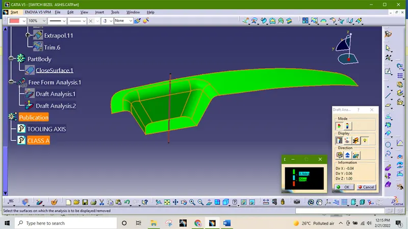
FINAL SOLID BODY DRAFT ANALYSIS
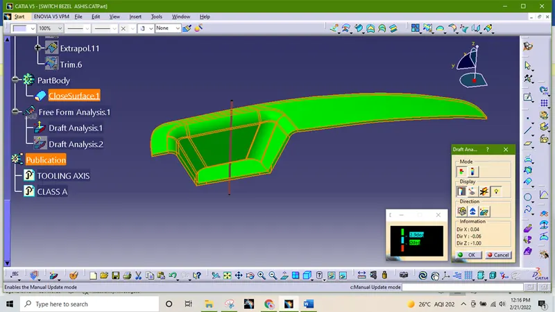
DESIGN VIEW OF DRAFT ANALYSIS
ISOMETRIC VIEW
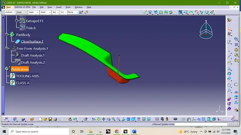
FRONT VIEW
RIGHT SIDE VIEW
TOP VIEW
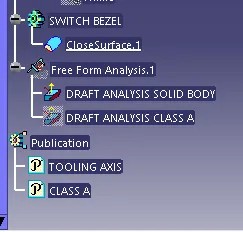
FEATURE TREE
CONCLUSION
The Class B, Class C and the solid body of the switch bezel is created from the given class A surface and the draft analysis is performed.