Week 8 - Challenge 3 - Switch Bezel Design
AIM: To create the Switch Bezel plastic component through the given Class-A surface
REPORT:
- For the given Switch Bezel catpart first we need to make the basic checks i.e. check the continuity of the part ensure that there is no gap between the surfaces we can take the help of surface command for this
- To obtain the Tooling Axis we will have to create tooling clearance axis in X and Y direction and bisect them
- To create the tooling axis clearing Y direction create a axis system and form a intersect of Switch Bezel Class A Surface with respect to the YZ plane
- Now create a point to point line on the faces that might create error and create a bisecting line between the two faces and we would get the tooling axis clearing Y direction
- For the tooling axis clearing X direction form a intersect of Switch Bezel Class A Surface with respect to the ZX plane and sketch a line at 6 degrees from centre and we would get the tooling axis clearing Z direction
- Now create a bisecting line using the tooling line clearing X & Y direction and we would get the Tooling Axis
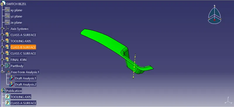
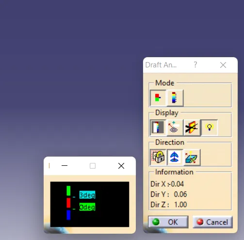
- For the draft analysis go to Insert-Analysis-Feature Draft Analysis and make sure the view mode is on material
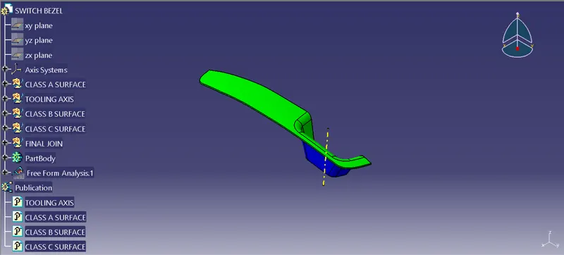
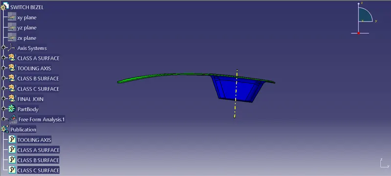
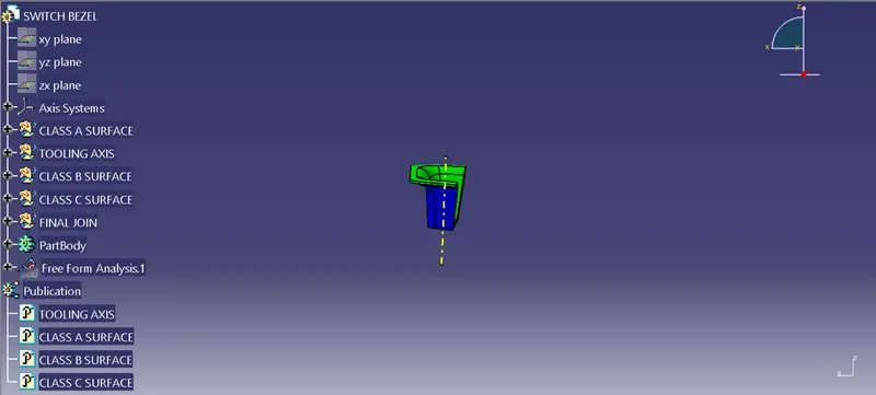
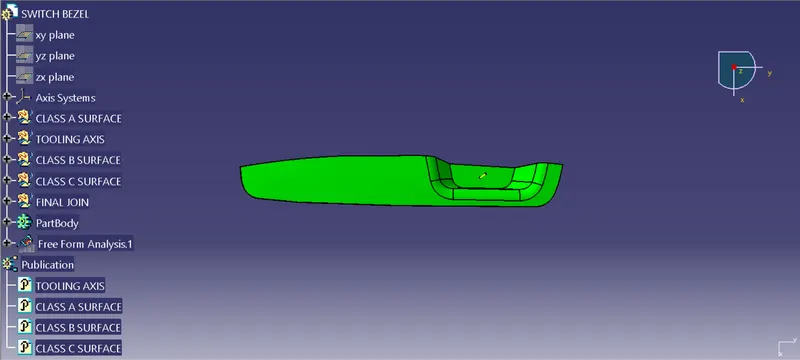
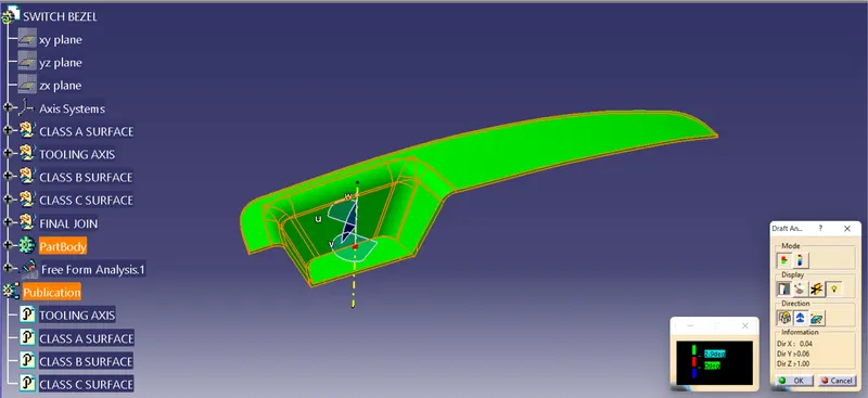
- Inline the compass with the Tooling Axis and lock then click on the Switch Bezel Class A Surface we will get the draft analysis for the Switch Bezel Class A Surface the minimum draft required is of 3 degrees
- When we click on the Switch Bezel Class A Surface it will turn green that means the required draft angle is maintained
- We can change the value of draft angle from the colour scale table and the Class A Surface will change the colour accordingly
- We can also analyse the draft at a particular point on the Class A Surface by moving the mouse cursor on the surfaces
- To generate the Class B surface extract the Class A Surface faces individually untrim them and offset at a distance of 2.5mm
- And finally trim the unnecessary faces and provide fillets we would get the Class B Surface
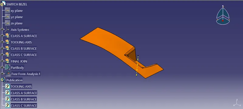
- To obtain the Class C Surface create boundary for Class A Surface and sweep it with 3 degree draft
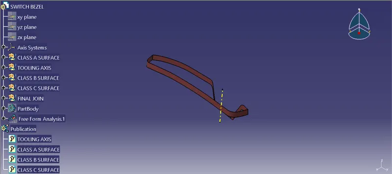
- To obtain the final solid Switch Bezel plastic component trim the needless surfaces and join the rest. Then use closesurface command to form solid component
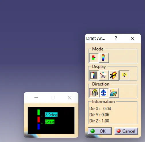
- At the end perform the draft analysis on the solid plastic component
- Also publish the Tooling Axis and Class A,B & C surfaces
Screenshots of the Draft analysis report for both the given Class-A surface and the final plastic component:
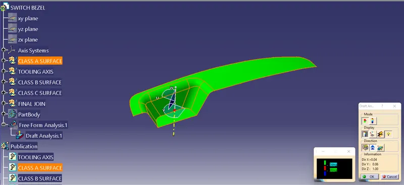
Screenshots of the solid model with the proper color code of the draft angle in various orientations (Isometric, Front,Side, and Top View):