Week 8 - Challenge 3 - Switch Bezel Design
1. Screenshots of the Draft analysis report for both the given Class-A surface and the final plastic component
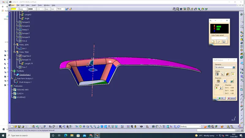
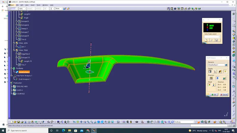
2. Screenshots of the solid model with the proper color code of the draft angle in various orientations (Isometric, Front, Side, and Top View)
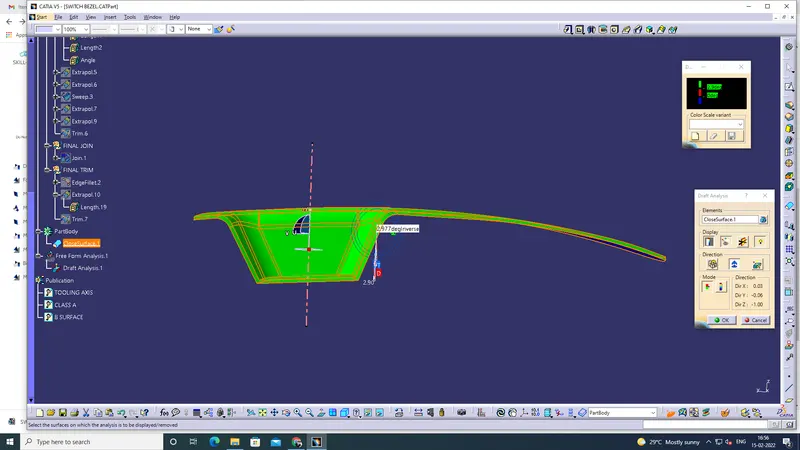
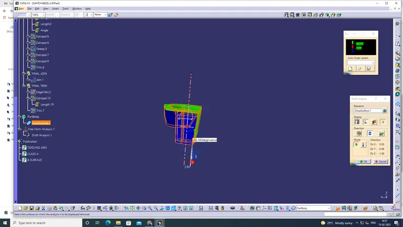
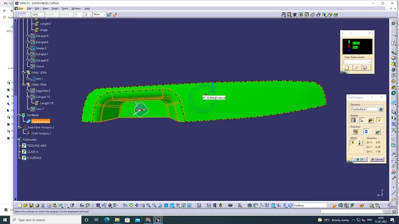
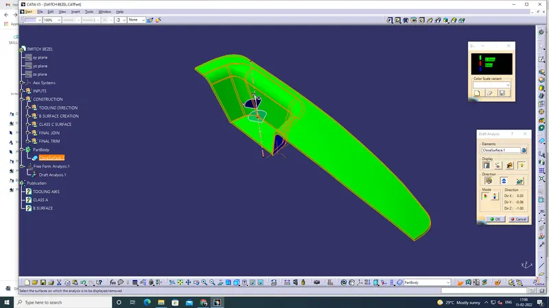
Expanation:
Tooling Axis
1. To correctly choose tooling dirrection for to create the tooling axis (x,y,z).
2. selected top view in z. (it covered all view)
3. select the base using multiple extract and to draw the 2 lines.
4. Using bisecting line depends on that 2 lines. sketch1
5. as the same process in another side and to create the 2 line, then using bisecting line depends on that 2 lines.
6. sketch1 and sketch2 depends create the bisecting line that is tooling axis.
7. Then check its all ok using draft analysis and rotation via.
8. Then Published the Tooling Axis and class A (given surface)
Class B Surface
1. (Rest surface) select the top faces and using extract, untrim and offset (3mm).
2. (wall) select the 3 faces and using extract, untrim and offset.
3. (Base) select the bottom face and using extract, untrim and offset.
4. then extrapolate in all Rest surface, wall and Base.
5. then using trim all surface should add while trim tool.
6. Then put the fillet in (Radius+distance) and Radius-distance) (check the measuring tool in class A surface as the same dimension)
7. Then check in all side.
Class C Surface
1. Take the surface in class A and check the boundary using curve smooth.
2. boundary is splited in to 2 using the curve smooth.
3. then put the sweep 1 and sweep 2 depends on the 2 curve smooth.
4. then check the gaps, if gap is observed means using extrapolate and trim to join the all faces.
5. check the connectivity using the boundary tool.
6. then unhide the class A and B. then join all the surface. (Final Join)
7. then unwanted surface should be trim and join using trim options (Final Trim)
8. Then check the boundary all ok means converted to part body
9. using close surface tool the surface becomes solid.
10. then order the tree structure and then publication in class b.
Draft Analysis
1. after the body in solid condition using draft analysis tool check the 3 colour dimensions (Green, Red and blue)
2. using compose drag and put in tooling axis.
3. then locked the compose and click the object its all in green.
4. So finally its all ok.
Errors:
1. when i check the draft analysis some surface observed red.
2. All dimensions are ok.
3. Then i changed the green value 2.9 and then i click the body green is blinked.
4. Challenge over. Ok.