Week 8 - Challenge 3 - Switch Bezel Design
Challenge 3 - Switch Bezel Design:
Objective:
Create the Switch Bezel Plastic component through the given Class-A surface. To begin with, the tooling axis for the given Class-A Surface should be created meeting the requirements of the draft angle and at the end perform the Draft analysis on the model.
Take the Thickness of the component to be 2.5 mm
Tool:
Catia v5
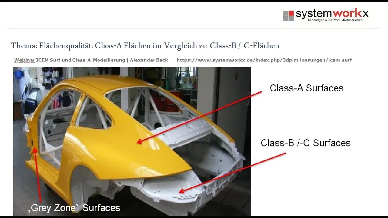
What is class a and b surface?
Class A surface is made from scanned data with different software like allias etc. Surfaces which is having CURVATURE CONTINUITY IS CALLED class-A. Class B surface: 1.invisible Surfaces. 2.Surface mostly don't have textures.
What is class c surface?
The Class C finish allows more imperfections than Class A or B. Class C is often specified for interior surfaces not readily visible, surfaces that will be covered by another part when assembled, or surfaces which the Customer feels do not need to meet a high cosmetic finish.
Designing process:
As a product devoloper i got a class a surface from styling team and now i'm gonna devolop the actual component from the class A so before that we need to have a tooling axis for create a component so, let's see how to we get that.

For create a line on x direction i've create a sketch on yz plane then i created line between the refference lines by bisecting method
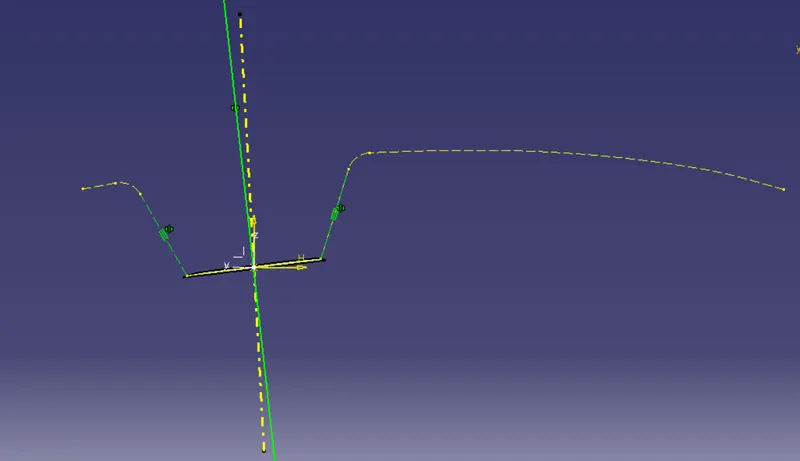
then same thing i did on the y direction but we have no complete surface in here we took a projection and create sketch and create another line respect to the horizontal direction in 4 degrees
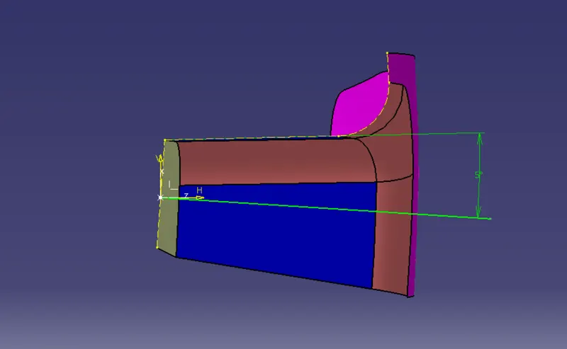
then i create a line between both the lines i created on X,Y directions so, now we got a tooling axis
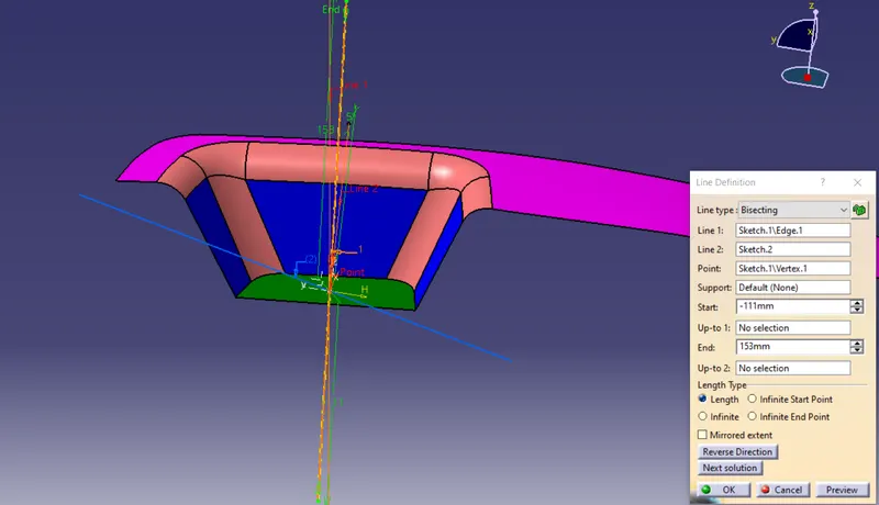
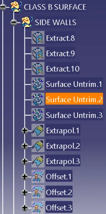
We got the tooling axis so let's go further for devolop class B surface i've began with creating the side walls
First i've extracted the side wall surfaces
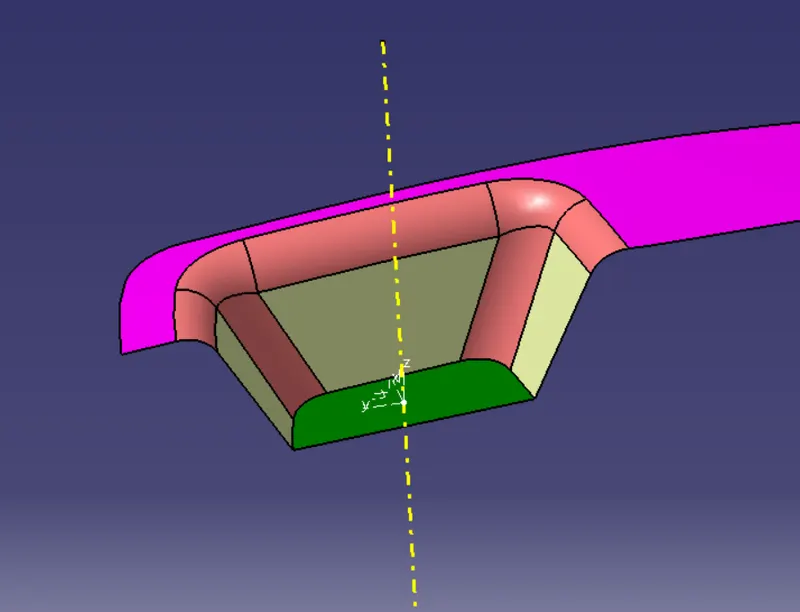
then untrimmed it
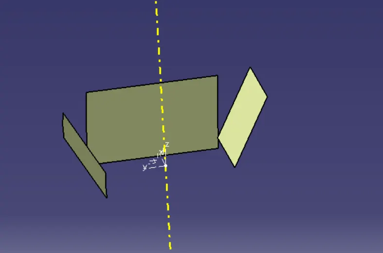
and extrapolated
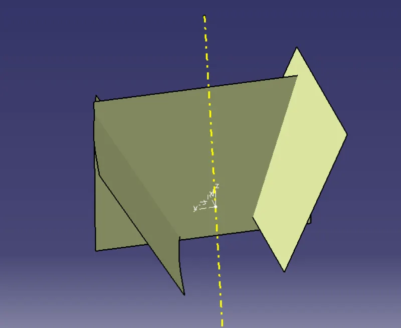
then offseted till 2.5mm since it's a required thickness of the component
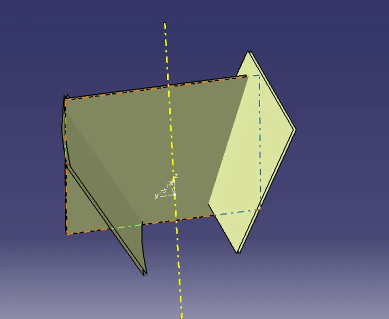
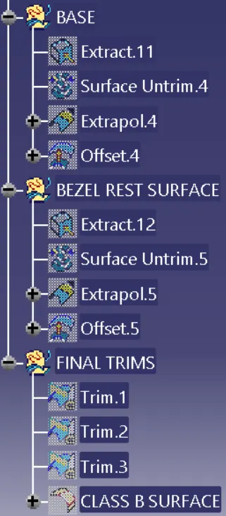
then i begin to create the base:
Same thing i did in here also first i extracted the base surface
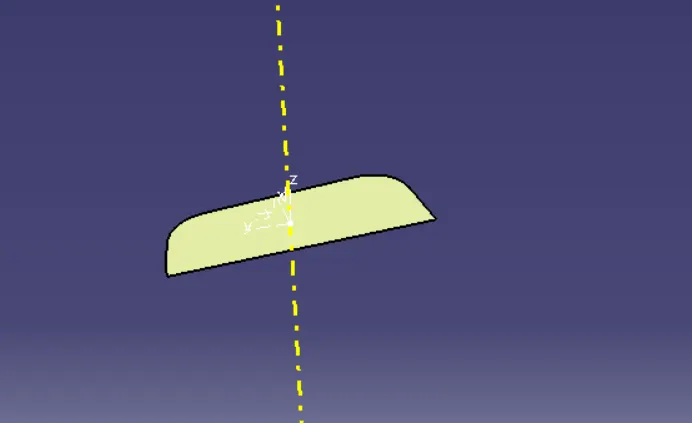
Untrimmed it
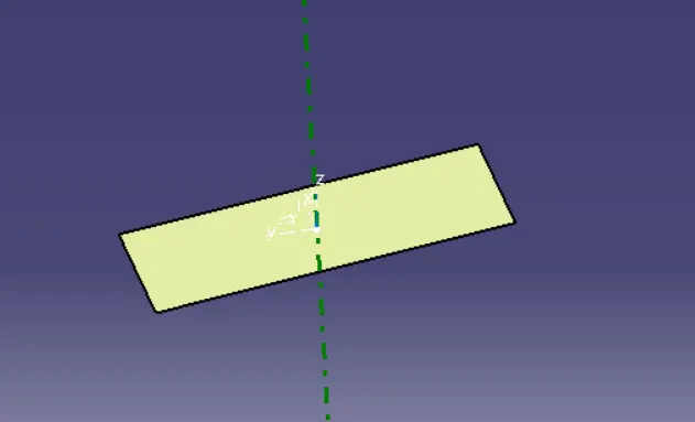
extrapolated itself
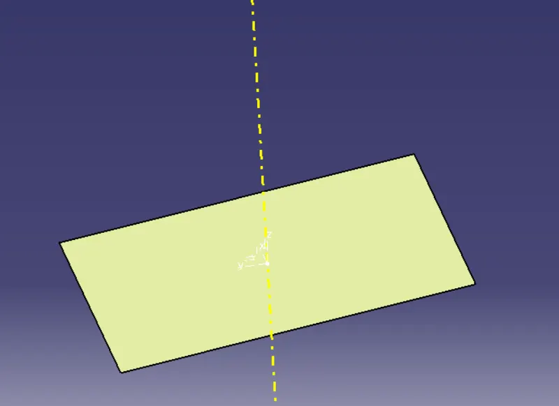
offseted 2.5mm
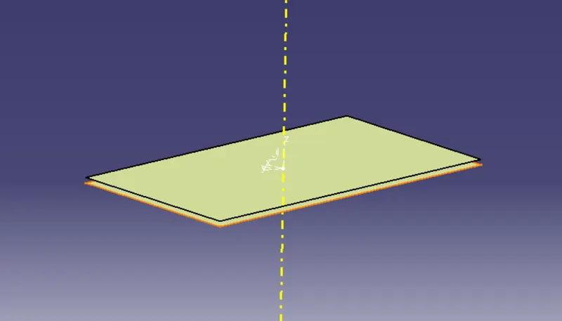
then i start to create a bezel rest surface:
Same thing i did in here also first i extracted the bezel rest surface
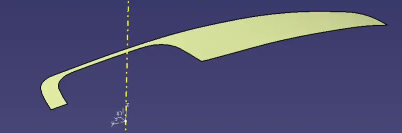
Untrimmed it
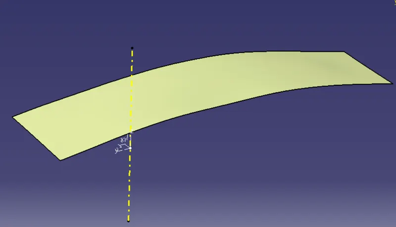
extrapolated itself and offseted 2.5mm
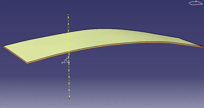
then first i trimmed the side walls and
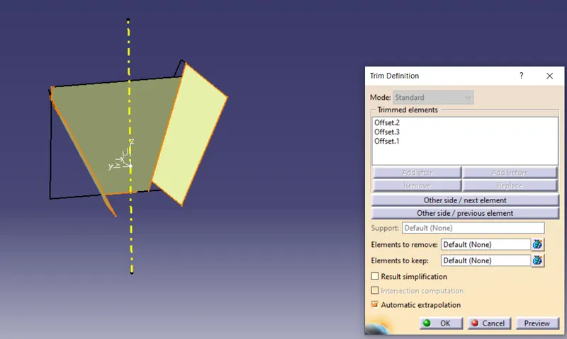
trimmed the base surface with side walls
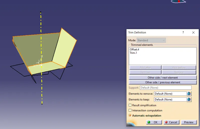
then trimmed with bezel rest surface
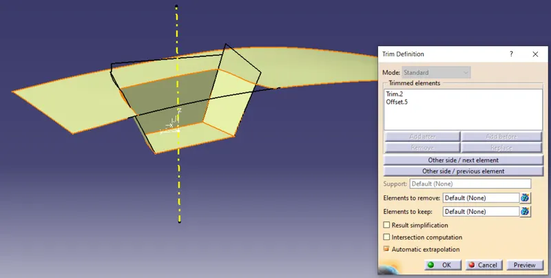
and edge filleted
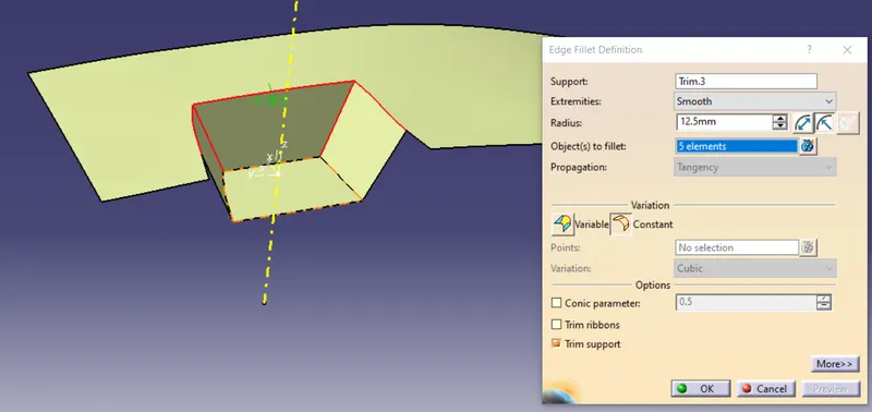
And we've got a class b surface
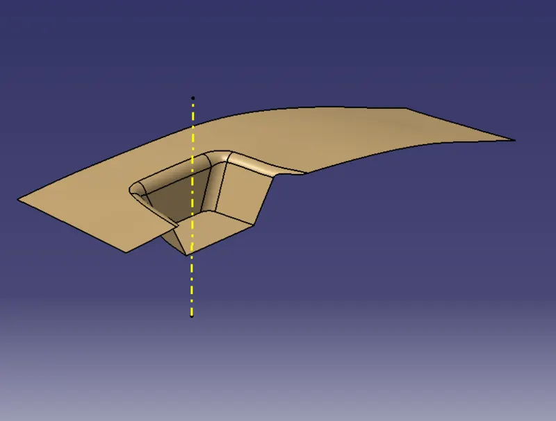
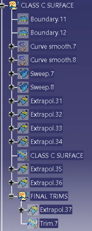
creating the class -C surface:
I took a boundry of class a surface
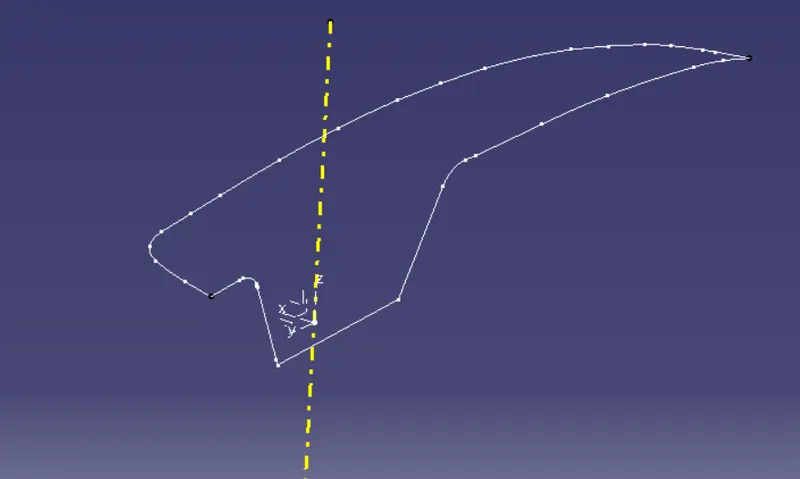
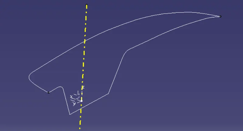
then i smooth them by smooth curves tool
then applied a sweep
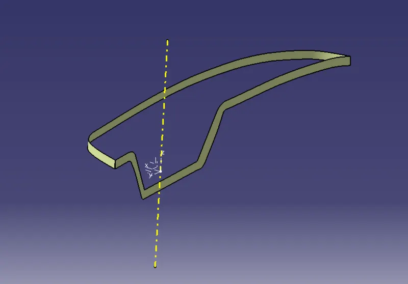
extrapolated on both sides
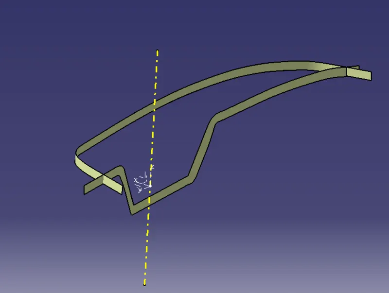
then trimmed it off
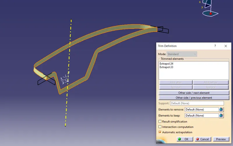
then in this case i had to extrapolate the class a and c surface to achive a proper closed surfaces on the edges of itself
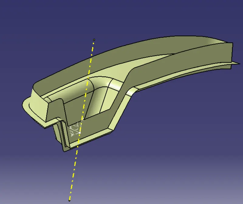
then i trimmed of
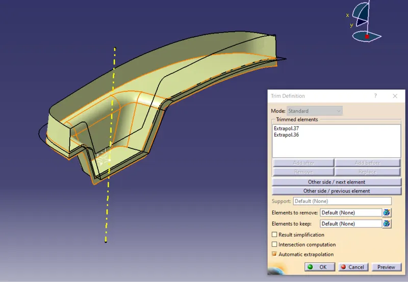
And eventually i trimmed with B surface of itself
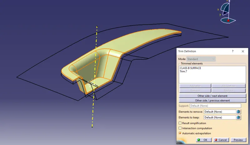
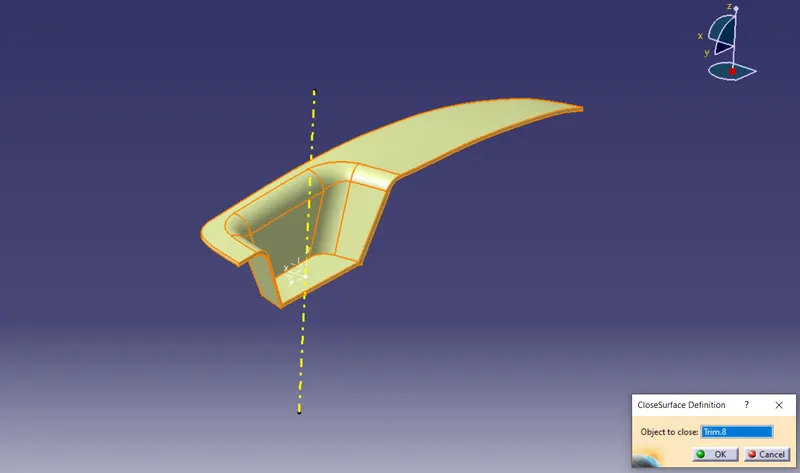
So, now we've got a perfect closed surface
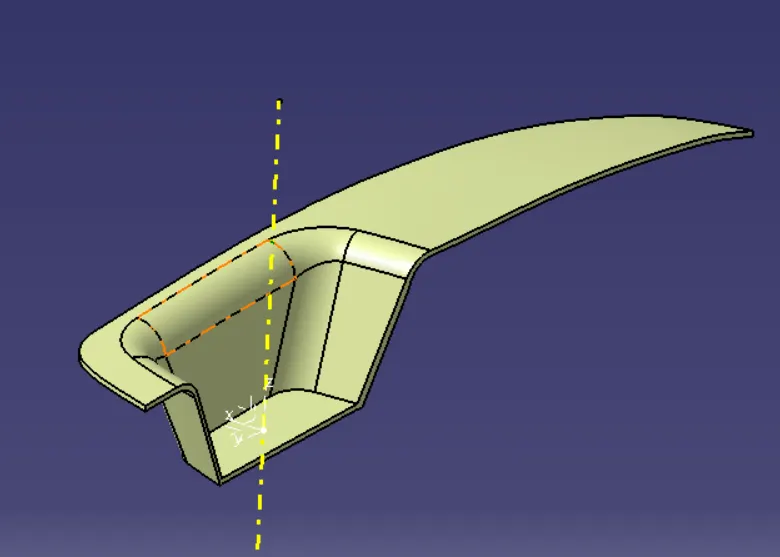
then solidifiying the component
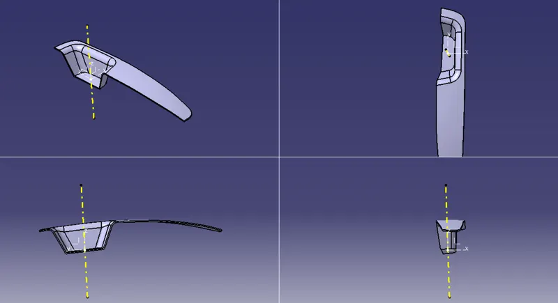
After that we having look at the component in multi directions
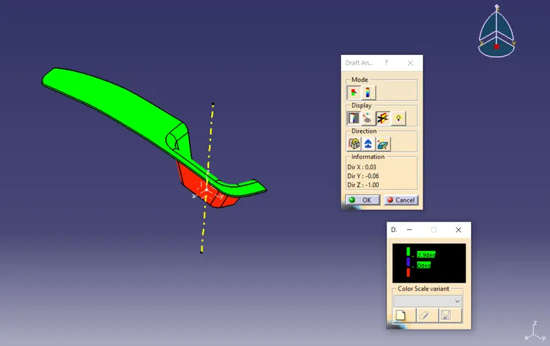
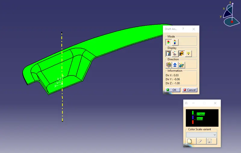
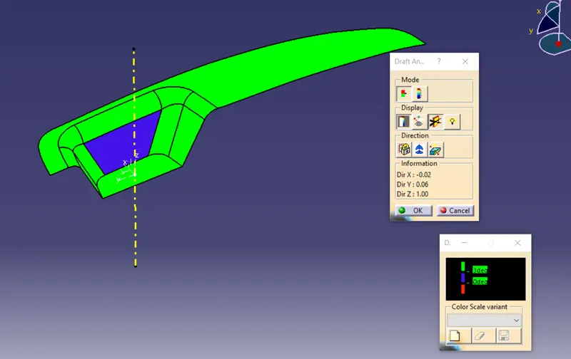
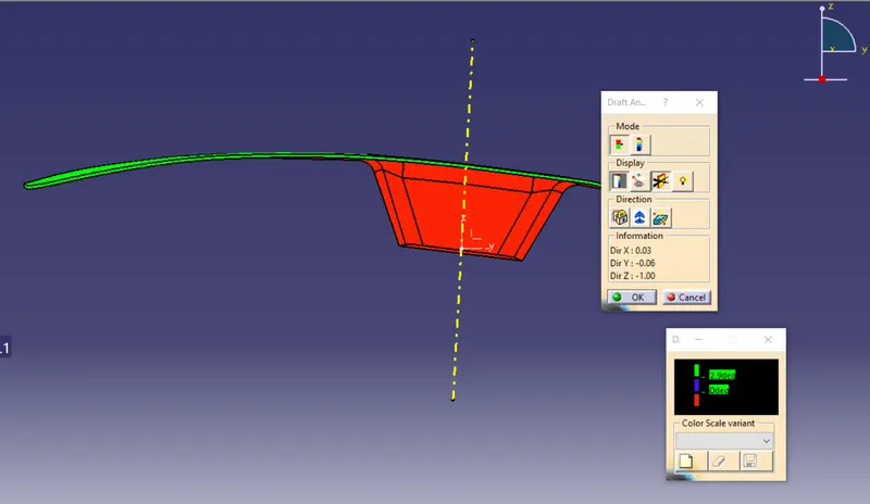
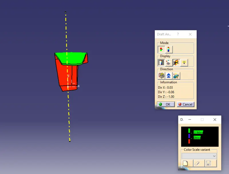
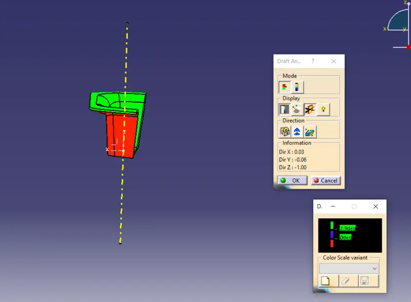
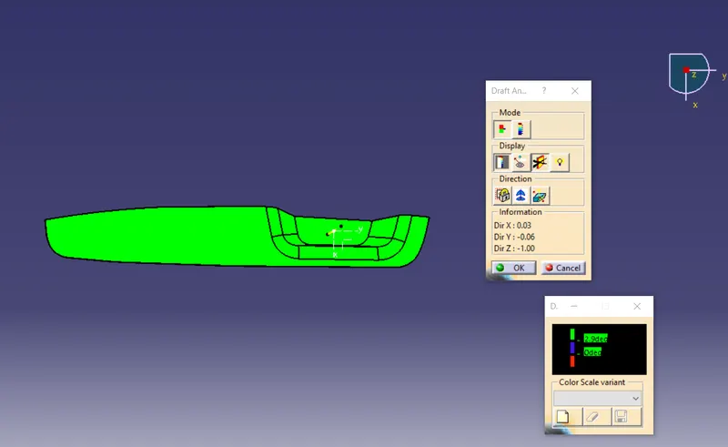
DRAFT ANALYSIS REPORT:
1) In this case after solidify the component i've take angle of tooling axis as 5 degrees and draft angle is 2.5 degrees for get 2)And it's draft analysis report of class a surface in this case i was took degrees of tooling axis as 4 degrees and all the sufaces get cleared in single tooling direction draft angle is 3 degrees.
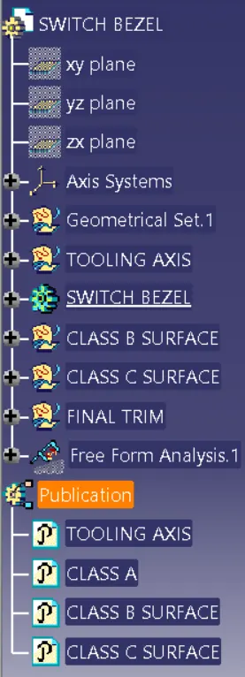
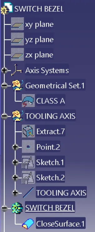
TREE STRUCTURE OF GEOMETRICAL SET:

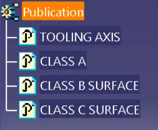
FEAUTURES THAT NEEDED TO BE BUBLISHED:
FRONT VIEW:
LEFT VIEW:
RIGHT VIEW:
TOP VIEW:
ISO-METRIC VIEW: