Week 8 - Challenge 3 - Switch Bezel Design
Objective:
The Objective of the project is to design the switch bezel and to do draft analysis by creating the required tooling direction with the help of bisecting method
Design Consideration
- Class A Surface should be aesthetically smooth and good
- Class B Surface should have all supporting features like ribs
- Class C Surface should also pass draft analysis
Class A Surface
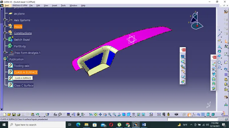
Creation of Tool Direction
Tooling axis defines the mold or core and cavity direction,we should create the tooling axis in such a way so that it should cover most of features,holes and geometry.we will check the suitable direction of the tooling axis through the visual inspection along x,y,z axis.
We are going to intersect the class A body with YZ plane so that we can use the line of intersection to create tooling axis with bisecting method.
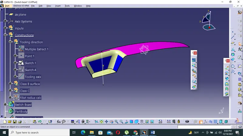
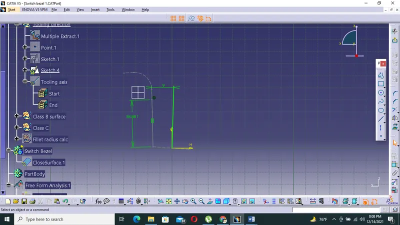
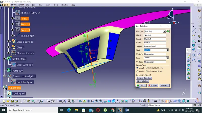
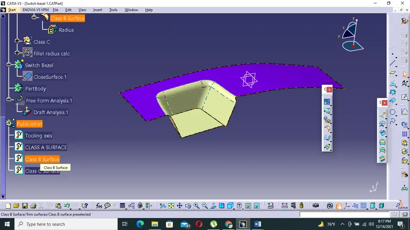
Creation of class B surface
- For creating class B surface except the offset surface has been extracted and untrimmed all the surface.
- Then all the surfaces extrapolated to get intersection between them
- Then the thickness size is 2.5 mm and the required corners have been filleted to 12.5 mm (15-2.5).
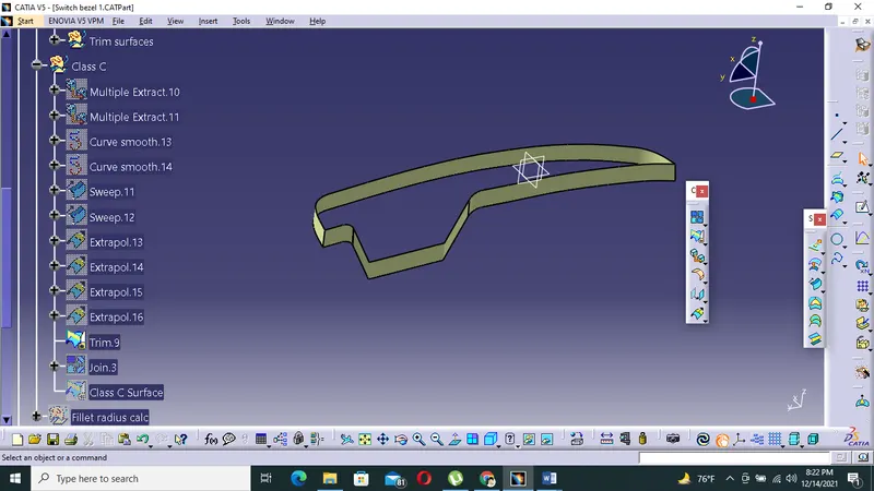
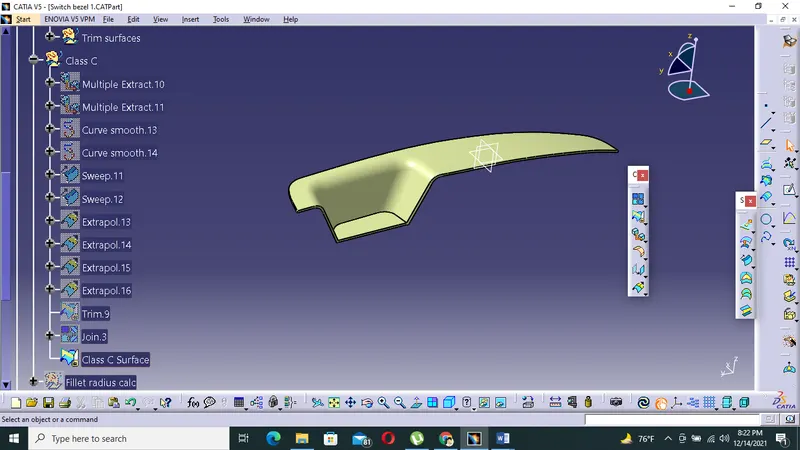
Creation of class C Surface
- The required outer edge of class A Surface were extracted using multiple extract.
- Then using sweep command the surface was created
- Then using extrapolated command the edges were intersected between the surface corners which ease the trimming operation
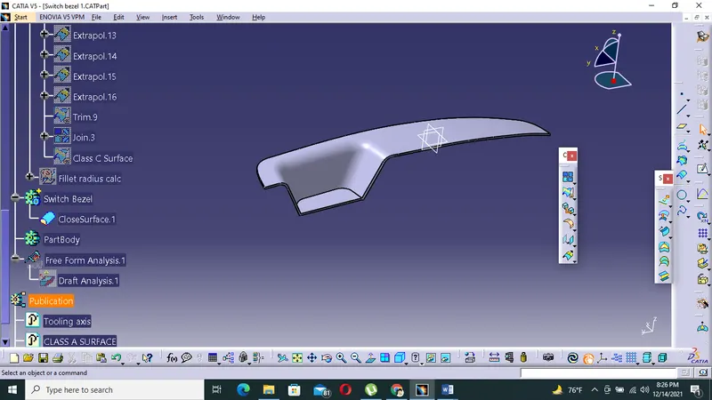
Creation of closed surface
By defining the part body by using closed surface command in part design,the component's solid body is created.
Procedure for Draft analysis
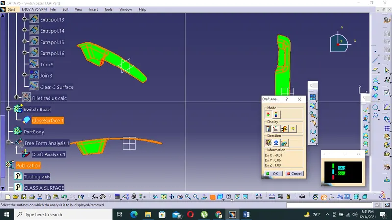
- By changing the view mode to custom view parameters-material mode then feature draft analysis is enabled
- Then the compass was activated and placed with the tooling axis by dragging the red pointer and then locking it
- The nominal value will be 3 degree draft angle and checked for component's draft angle
- The green coloue area show it statisfies the 3 degree draft angle.If not statisfied,then by using running point tool the area is measured and then altered to get a successful draft for the created tool direction.
Conclusion
Thus the class B and class C is made out of Class A surface and performed draft analysis on the model.