Week 8 - Challenge 3 - Switch Bezel Design
DESIGN OF SWITCH BEZEL
OBJECTIVE: The main objective of this challenge is to performe draft analysis on given class A surface and to develop a final solid switch bezel part and perform the draft analysis on the solid part by using CATIA v5 software. A report has to be prepared by explaining about what is draft analysis and tooling axis and add all the relevant images to the report.
DRAFT ANALYSIS
Draft analysis is a analysis which is performed on the objects or bodies in order to check the draft angle of various faces in a particular direction which is tooling direction.
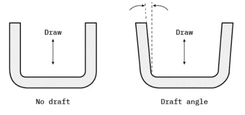
Every part like sheet metal parts which are generated from a Press Tool or some forming tools, may be the plastic parts which generally come out from the plastic moulds and maybe the casting parts, all such kind of parts required some drafted face on the surfaces which are parallel to the tooling direction. If we don't provide drafts on the surface then it will stick to the mould surface and whenever the mould is in motion they will destroy the surfaces or also reduced the finishing of surfaces.
The Tooling Direction is basically the direction that the mold pulls apart. The mold is built in two separate pieces, basically. You have a Cavity side and you have the Core side. The Core pulls apart from the Cavity and that's the Dyeline or the Tooling Direction.
And the axis which represents the tooling direction is called tooling axis and selection of this is axis is a crucial step while performing the draft analysis.
CLASS A SURFACE:
In automotive sector, a class A surface is any of a set of freeform surfaces of high efficiency and quality. Although, strictly, it is nothing more than saying the surfaces have curvature and tangency alignment – to ideal aesthetical reflection quality, many people interpret class A surfaces to have G2 (or even G3) curvature continuity to one another.
Class A surfacing is done using CAD applications. Class A surface modellers are also called "digital sculptors" in the industry. Industrial designers develop their design styling through the A-Surface, the physical surface the end user can feel, touch, see etc.
In general CLASS A surfaces are crated using autodesk alias software.
CLASS B SURFACE: Class B surfaces are the secondary surfaces that you can see sometimes, but are less important, such as the inside of your glovebox, ash tray, etc.. These must be smooth and "error-free" as well, but are not held to the standards that class A surfaces are.
CLASS C SUFACE: The Class C finish allows more imperfections than Class A or B. Class C is often specified for interior surfaces not readily visible, surfaces that will be covered by another part when assembled, or surfaces which the Customer feels do not need to meet a high cosmetic finish.
CREATION OF TOOLING AXIS
1. First extract the base surface of the given class a surface and create a point at the centre of the surface.
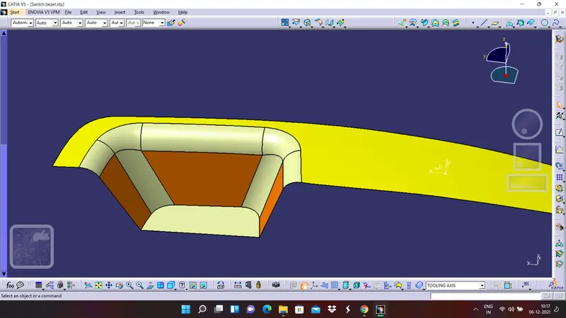
2. Now create an axis system based on the point which we have created earlier
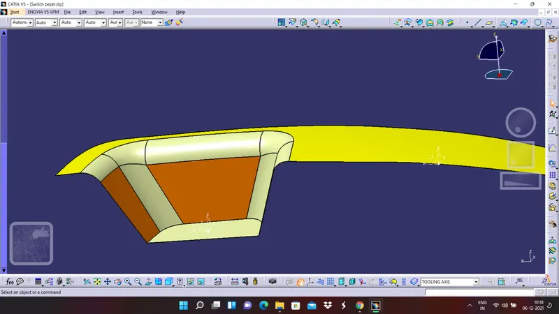
3. By using positioned sketch and YZ plane as a reference create a sketch and by using intersection command in sketcher workbench create an intersection as shown below,
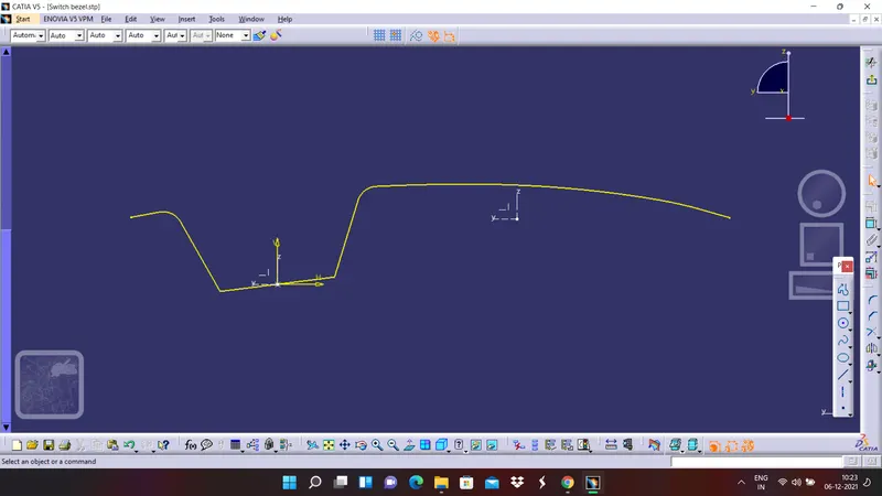
4. Now create two lines which are passing through the intersection curve as shown below make them as construction element and using line commnd and type as bisecting create a bisecting line between the tw lines.
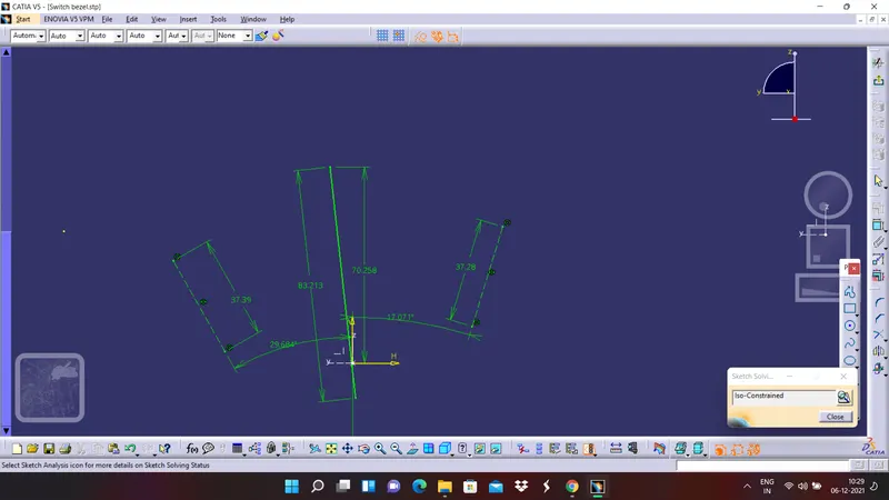
5. Create another sketch by taking ZX plane as reference and create another line as shown below,
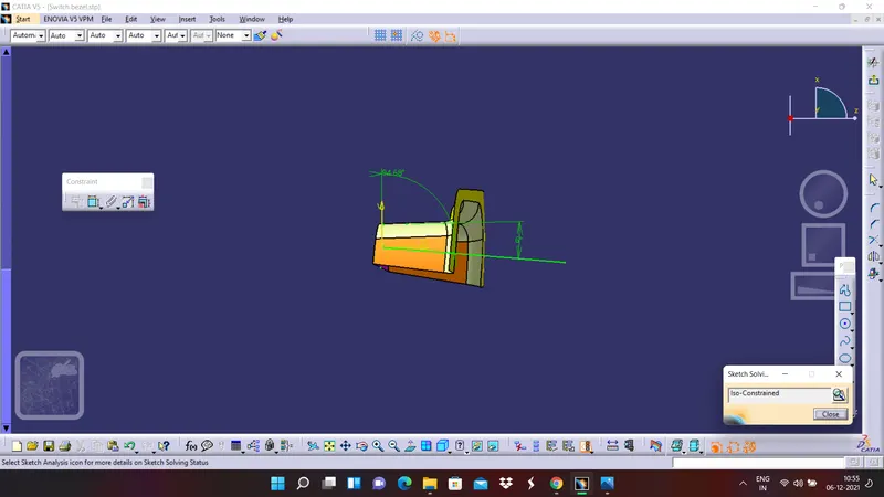
6. By using bisecting line create a line by selecting the lines in the two sketches and name the resultant line as tooling axis line.
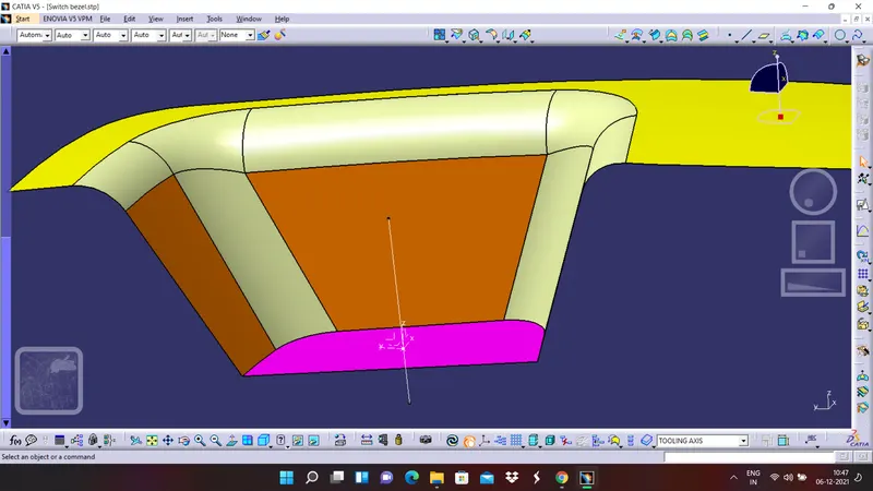
CHECK FOR TOOLING AXIS
We can verify thet the tooling axis which we have created is correct or not in a very simple manner. For that,
1. select the tooling axis which we have created.
2.now click on the normal view tab and if we see tha three walls in that view then we can say that our tooling axis is correct or else we have to modify the tooling axis.
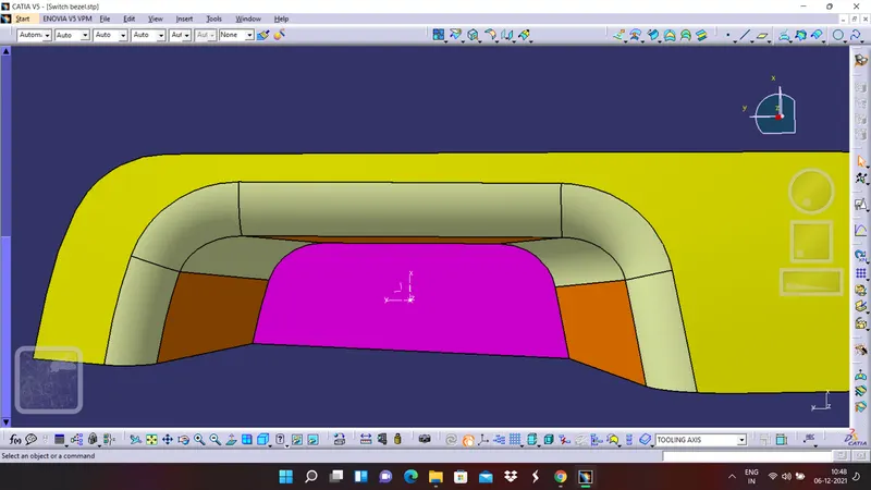
DRAFT ANALYSIS ON CLASS A SURFACE
The class A surface after applying the colours to different surfaces looks as shown in below image,
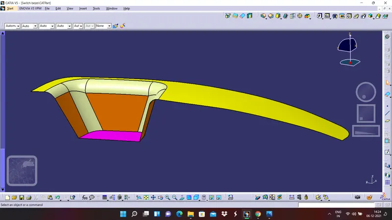
1. Open the draft analysis tool and set the value of draft as 3 degrees and ensure the surface is in material mode in customize view tool bar.
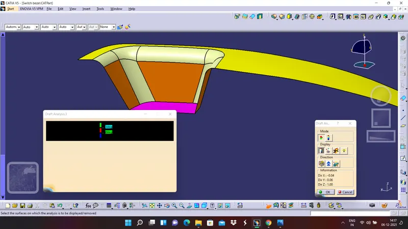
2. Click on the compass command which is in the direction command and align the compass and our tooling axis properly and click on the lock symbol and just tap anywhere on the class A surface and we will gwt the draft analysis. The images of the draft analysis in different views are as shown in below figures,
ISOMETRIC VIEW:
FRONT VIEW:
SIDE VIEW:
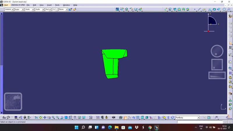
TOP VIEW:
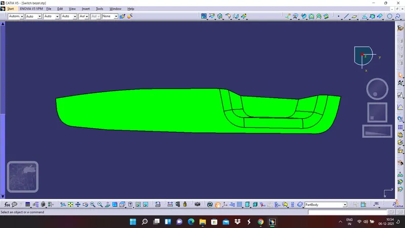
CREATION OF CLASS B SURFACE
The B surface of the part has three parts within the B surface, they are
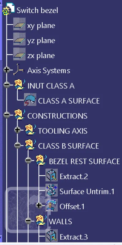
- BEZEL REST SURFACE
- WALLS
- BASE SURFACE
BEZEL REST SURFACE:
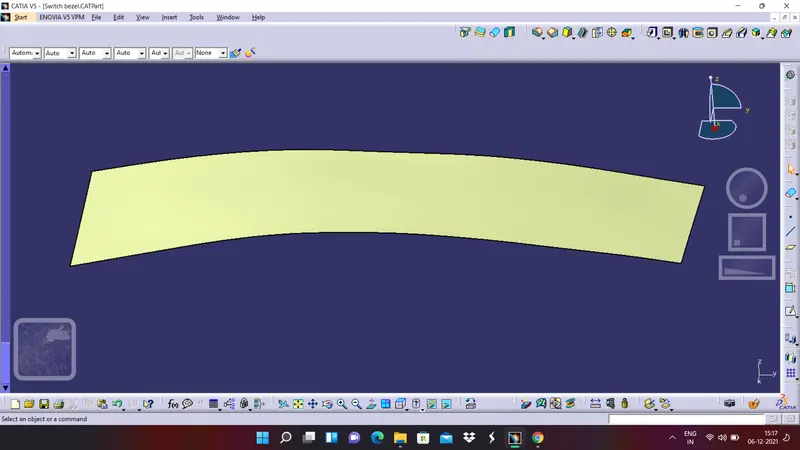
1.For bezel rest surface extract the surface of the bezel rest from class A surface
2. Untrim the surface.
3.Offset the surface to a distance of 2.5 mm in downward direction.
WALLS:
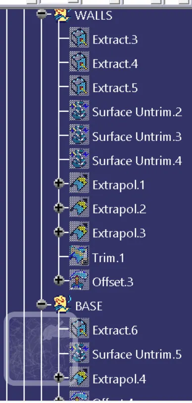
1.Extract the three walls of class A surface.
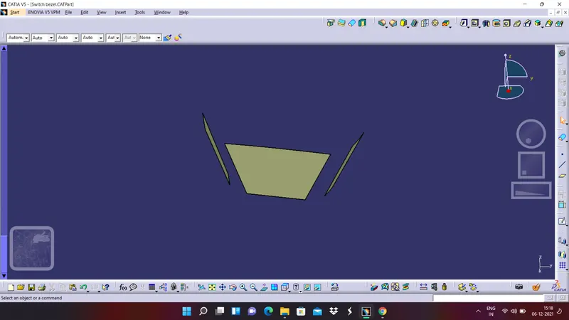
2. Untrim the walls.
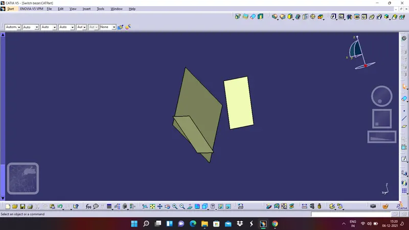
3. Extrapolate the three untrims and make sure they are extending with curvature continuity and propagation mode as point continuity.
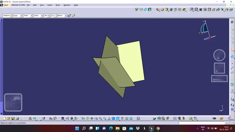
4. Trim the walls to make a shape similar to the given class A surface and offset that to 2.5 mm in proper direction.
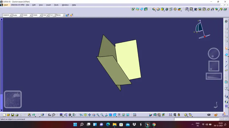
BASE:
1. Extrct the base and untrim the base.
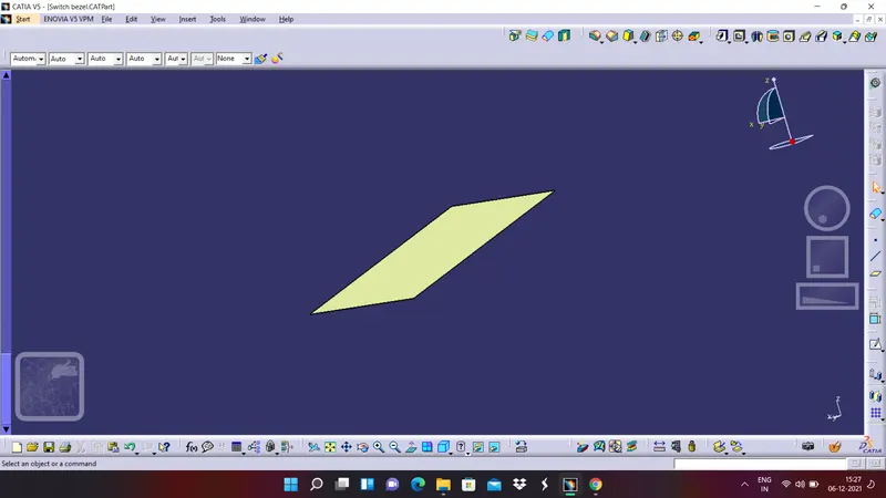
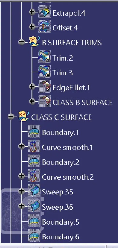
2.Extrapolate the base and offset it to 2.5 mm and trim it with walls and bezel rest surface.
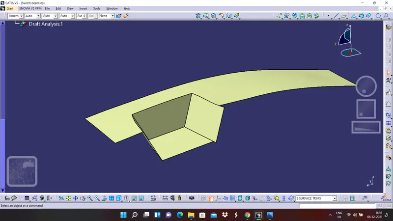
3. Apply fillets with proper radius and rename the last edge fillet as CLASS B SURFACE.
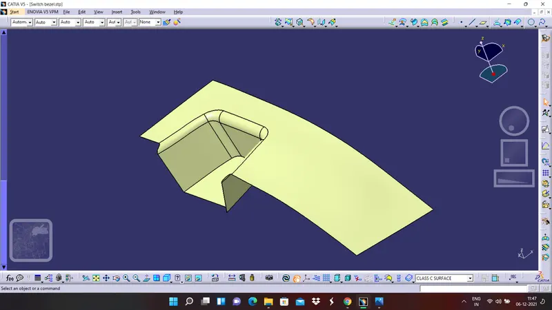
CREATION OF CLASS C SURFACE
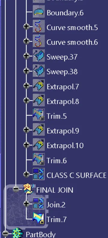
1. By using boundary command create a boundary to the surface.
2. divide the boundary into four parts and sweep the surfaces.
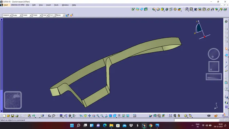
3.Now extrapolate the edges where there are gaps and trim them and join them together in order to create a final CLASS C SURFCE.
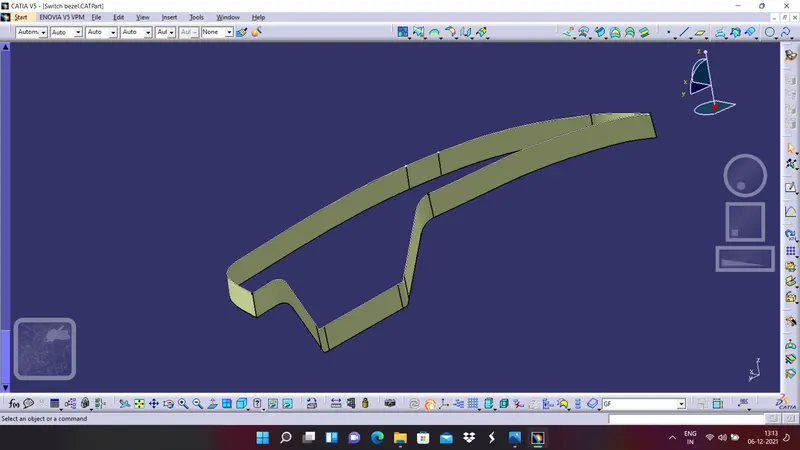
Now after that join class A and class C and after that trim it with class B and it is like as shown in below figure,
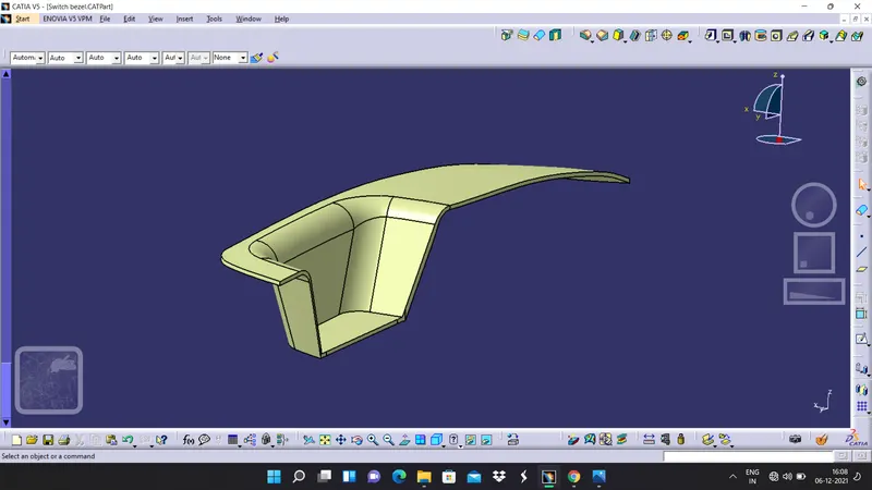
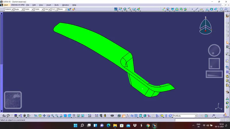
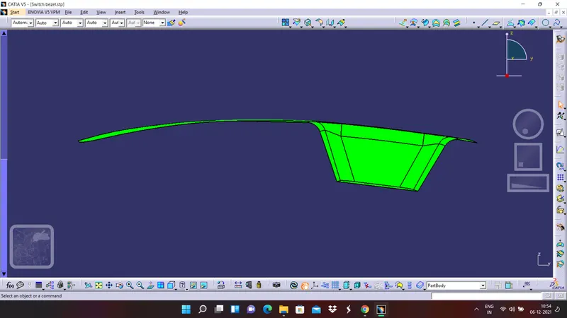
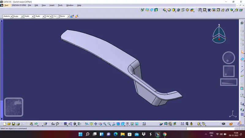
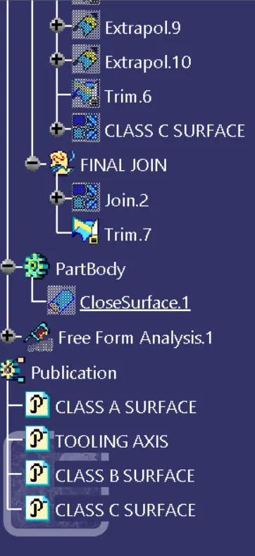
By using close surface command fill the gap and create a solid, the views of solid are as show in below figures
ISOMETRIC VIEW:
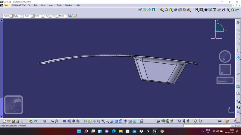
FRONT VIEW:
SIDE VIEW:
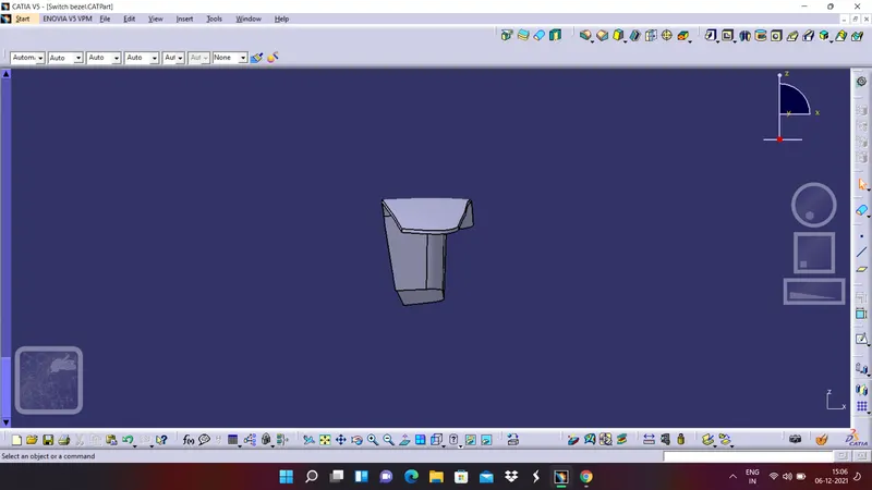
TOP VIEW:
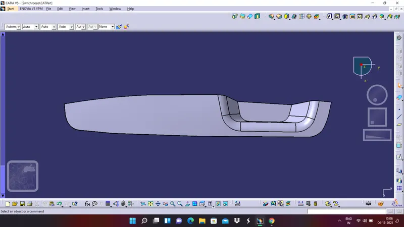
DRAFT ANALYSIS ON SOLID BODY
ISOMETRIC VIEW:
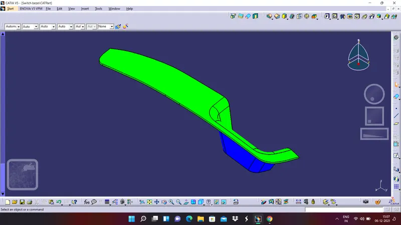
FRONT VIEW:
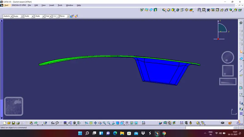
SIDE VIEW:
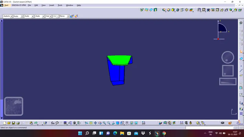
TOP VIEW:
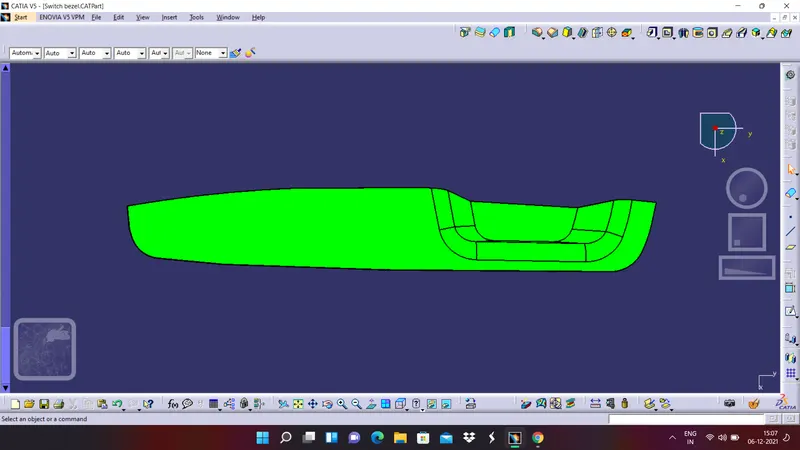
PART NAVIGATOR
CONCLUSSION
And hence we are concluding that the swith bezel design is completed successfully. draft analysis is performed on the part and it is satisfied the draft angle required and a report has been prepared by attaching all the relavent images.