Week 8 - Challenge 3 - Switch Bezel Design
AIM: Creating switch bezel plastic component using a given class A surface
OBJECTIVE :
- To create class C and Class b Surface for the given component
- to create a tooling axis for the given component
- to perform draft analysis on the plastic component
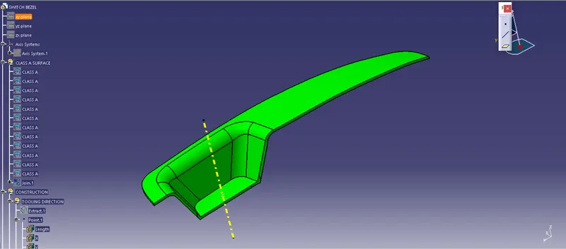
TOOLING AXIS :
- Extract the base surface and create a reference point on the surface
- make a dummy axis point on that reference point and create a positional sketch on the z-x axis
- project the boundary of the class a surface on the sketch plane
- create 2 lines on the inclined lines and then create a bisecting line using those two lines
- make everything else construction line in that sketch other than final bisecting line
- do the same sketch process on the xz direction, but here we don't have an inclined line so use the centre reference point and create a line on z-direction and give it an inclination of 6 degree
- using these two lines from sketches 1 and 2 create another bisecting line and name it as tooling axis
- change the properties of the tooling axis and publish it along with the class a surface
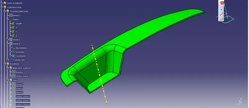
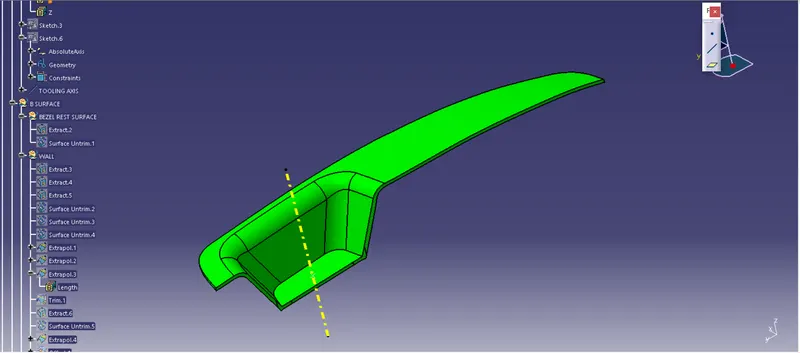
CLASS B SURFACE
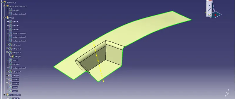
- Extract the required surfaces and untrim them all
- use extrapolate to intersect them with one another
- since the switch bezel has a thickness of 2.5mm, offset the extrapolated surface to an offset of 2.5mm and hide the extrapolated surfaces
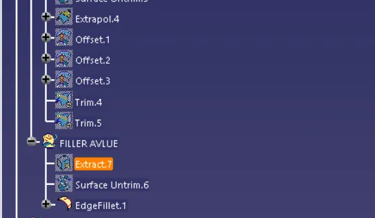
- trim all four surfaces with one another
- add edge fillet of 15mm along with the thickness of 2.5mm
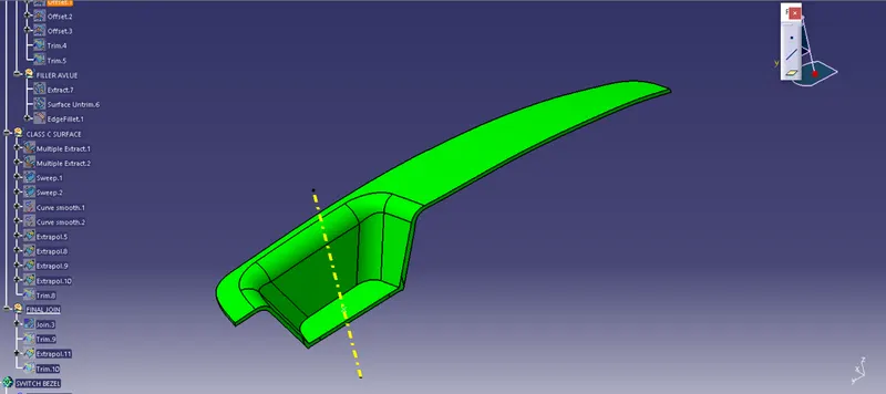
CLASS C-SURFACE CREATION
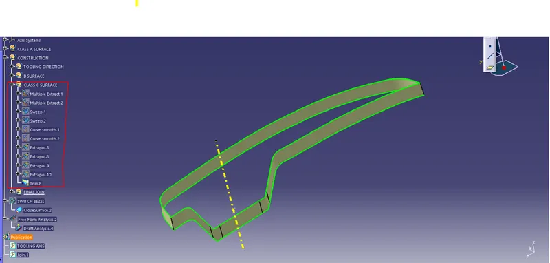
- EXTRACT THE REQUIRED OUTER EDGES FROM THE CLASS-A SURFACE
- then by using the sweep command surface was created and the curve was smoothed using the curve smooth command
- then by using extrapolate command extrapolate the edges of both surfaces and trim them
CLOSED SURFACE
- now we have to create solid body for that we first have to join the class-A and class-C surface together using the join command
- then trim the joined surface with the class-b surface
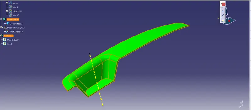
- then using the command closed surface we have a closed body
DRAFT ANALYSIS
- The Draft Analysis command enables the user to detect if the part that the user drafted will be easily removed.
- This type of analysis is performed based on colour ranges identifying zones on the analyzed element where the deviation from the draft direction at any point, corresponds to specified values.
PROCEDURE
- first, check if the model is in material mode
- then click on analysis and select feature draft analysis
- select the compass and align it with the tooling axis created before
- now green colour will appear on the model which signifies that it can be made under the given draft angle
- we can change the draft angle in the colour tab by double-clicking it .. optimum draft angle is 3degree
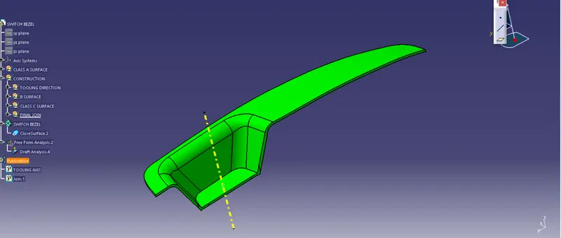
FEATURE TREE