Photo Realistic Rendering
TITLE: DESIGN, MODELLING, ASSEMBLY AND PHOTO-REALISTIC RENDERING OF AN AMERICAN CHOPPER
OBJECTIVE: The objective of this course is to get an understanding of basic Solidworks tools for designing, modelling and assembly of parts
INTRODUCTION: This report consists of an elaborated explanation of designing American chopper starting form part modelling to the final rendering of the assembly.
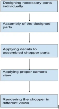
DESIGN METHODOLOGY: flow chart
DESCRIPTION:
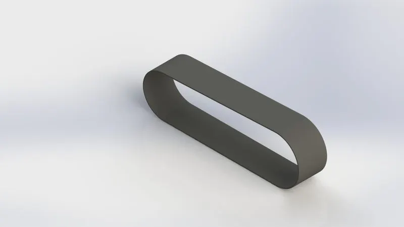
- Transmission belt: Belt is used as a source of motion to transmit power efficiently from engine output shaft to gearbox.
The profile of the transmission belt is created as per the dimensions on the front plane and an offset of 3 mm is given to the whole sketch in an outward direction. By using features like extruded boss/base we extrude the surface to given dimensions and the fillet is added to the edges.
Features : Extrudedboss/base,fillet
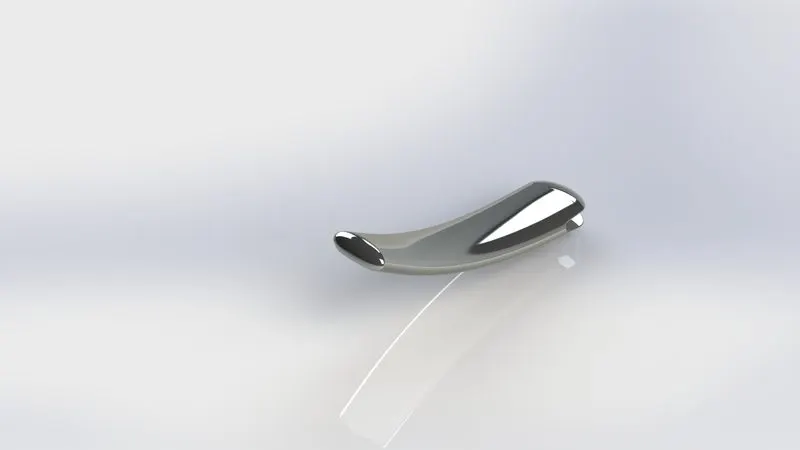
2. Kick Stand: It is a supporting structure provided to two-wheeler vehicles to help it stand vertically when parked
Initially, two ellipse sketches are created on the right plane and required dimensions are given in order to make it fully defined. these two ellipses signify the top and bottom end of the kickstand
Now a spline sketch is created on the front plane with required dimensions and making it fully defined. This spline should pierce both ellipses at the centre. The loft feature is used to create the base body of the kickstand. Elliptical dome feature is used on both ends of the stand to create a rounded surface. A slot with an extruded boss feature is created on the top end of the stand where it is to be connected to the chassis. Fillet feature is used on the sharp edges of the stand. For appearance, the chrome plate is given to the kickstand.
Features:lofted boss/base,dome,extruded cut,extruded boss/base,fillet
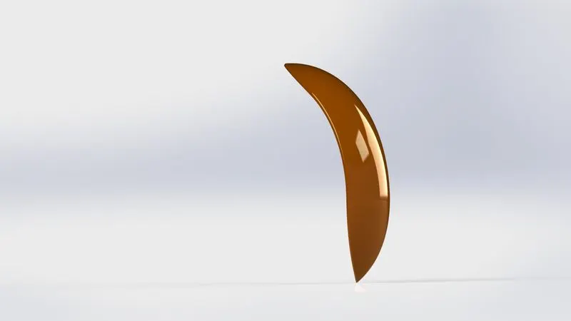
3. Front fender: It is used to prevent sand, mud, rocks etc from being thrown into the air by a rotating wheel.
The sketch is created on the front plane using a three-point arc with required dimensions along with a reference line which will come in handy in a later stage. By using the revolve command reference line and with the help of required dimensions we will create a basic fender shape. Now on the centre plane create a sketch using spline and dynamic mirror option. Using the split feature remove the unnecessary parts from the fender body. again create another sketch on the front plane by using the spline and dynamic mirror option. Then again use the split feature to remove unnecessary parts. Now use the fillet option of the required dimension on the edges. Apply the required appearance on the front fender.
Feature: revolved boss/base,split,shell
4.Rear fender: It also serves the purpose of protection from the rear wheel end of a vehicle.
The sketch is created on the front plane using a three-point arc with required dimensions along with a reference line. using revolve feature along with dimensions a base fender body is created. fillets are created on sharp edges as per the dimensions. The desired appearance is applied
Feature: revolved boss/base, fillet, shell
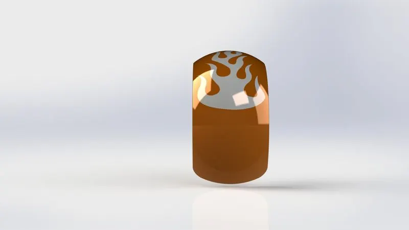
5. Chain: It is used to transmit power from the engine to rear wheel. It is connected to the sprocket on the rear wheel.
Initially, default planes are renamed as follows:
1 front plane = midplane chain
2 top plane = centre plane chain
3 right plane=front plane chain
The base sketch is created using 3-point arc and tangent relation between arc and lines and then required dimensions are given. Two throwaway sketches are created which are used as inner and outer plates of the chain using required dimensions. These throwaway sketches are created and saved as blocks for easy usage due to multiple repetitions of the same sketch. After importing the two-block sketch align them by coincident and concentric relations with the base sketch. Now using extrude boss/base feature extrude the pins with given dimensions and remember to not merge pins. now again use the same feature and extrude the plates part and again deselect merge option. By using curve driven pattern feature populate it over the first contour base sketch. For a smooth chain model, we have to perform the same process for the remaining 3 contours. As the end link will not merge with the first one, delete the last link and using sketching option make a link manually and then extrude it. Separate pins from plates for easy access and usage. mirror all the plates on the opposite side by using mirror option and midplane chain as a reference plane Lastly desired appearance is added to the chain.
Features: Extruded boss/base, linear pattern, circular pattern, fillet, mirror, combine.
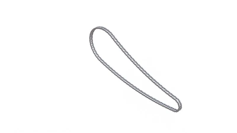
6. Oil tank: It is the storage unit of the motorcycle which stores engine oil which ensures smooth running
We start by renaming our default plains as following
1.front plane=mid plane oil tank
On the top plane create a sketch using 3-point arc and lines and use tangent relations. extrude the sketch using given dimensions and we will get a base structure of the oil tank. Now on the front plane create another sketch and make it fully defined using given dimensions. Now extrude the sketch using the midplane extrude option by deselecting the merge option. Now by using combine operation and keeping type as common it will combine both bodies after deleting unnecessary parts. Use the fillet option for sharp edges with required dimensions. select shell feature with required dimension but without selecting any face click ok (this basically makes the oil tank hollow ).lastly select Siena car paint as appearance for the oil tank.
Feature: extruded boss/base,combine,shell and fillet.
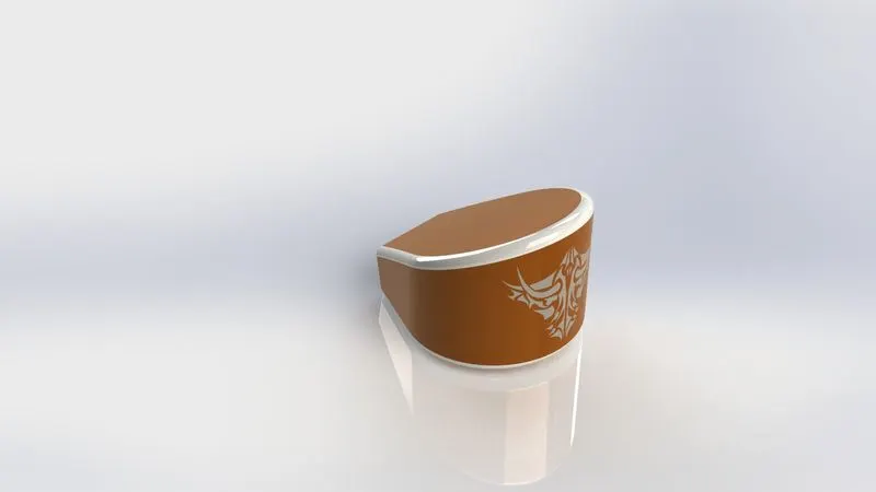
7. Pedal: It is the part of the motorcycle where gears and brakes are easily available for the rider while riding the motorcycle it also plays a role as a footrest for the rider
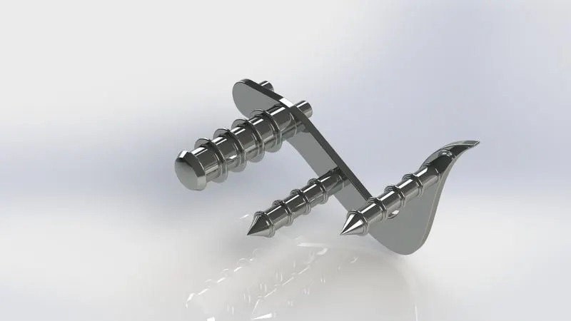
Create a sketch on the front plane by using the given dimensions to make it fully defined. Extrude the sketch to make mounting pins up to the required distance. again select the same sketch and extrude the main structure. On the top plane make another sketch which will be our footrest/extruded cylinder with given measurement. By using the revolve command on the previously created sketch we get our footrest/extruded cylinder. boss extrude other two circular sketches parallel to the first extruded cylinder. use dome feature on the end of the extruded cylinder 1 without selecting the merge elliptical option. now create a sketch on the front plane and use convert entities to convert the circular edge of previously created extruded cylinders
Feature: extruded boss/base, revolve boss/base, dome, linear pattern, chamfer, fillet
.
8.Front-wheel: The front wheel helps to guide the direction of the vehicle when the direction of the handle is changed.
Initially, a rim sketch of the wheel is created on the front plane using the required dimensions and reference lines. After which revolved feature is used to extrude the base sketch. A spider web design (spokes) of the rim is created on the front plane and is extruded by keeping the midplane extrude feature. Now by making ribs geometry which connects extruded spokes of rim .then we created a sketch on a right plane in order to remove material from the wheel and to give it a curvature. now by using a circular pattern whose distance is equally placed from each spoke is according to dimension and a total of 3 are created. by using combine feature option and adding all 3 spokes with the rim and centre cylinder is created as a single body
1.rotor: select the front plane and make a sketch on it with given dimensions. Use the extrude feature to extrude it to given dimensions now by selecting the face of the rotor as reference make necessary holes and then use the extrude cut option and then use circular pattern feature for required design.
2.Brake calliper: take the front face of the rotor as the reference plane create a sketch using lines with given dimensions. use extrude feature after which apply necessary fillest to edges and also apply chamfers to complete the calliper lastly apply Siena paint for appearance.
3.tyre: create a sketch by converting entities of the rim on the front plane. Complete the sketch and then use revolve feature to create the outer surface of the tyre. For the tyre, threads select the front plane and make the necessary sketches
Using relations and dimensions. Use extrude cut feature and give offset of a given dimension. After that, use a circular pattern for covering the whole tyre with threads.
Features: extruded boss/base,circular pattern,extrude cut,combine,revolved boss/base,revolved cut,chamfer,fillet
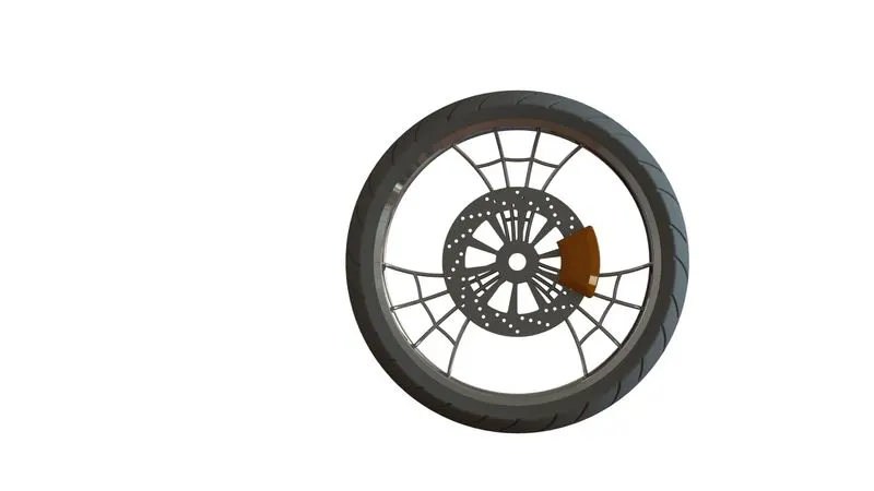
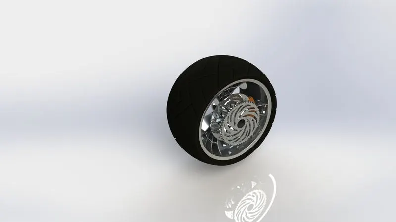
9.Rear wheel: component of the vehicle which helps in the motion of the vehicle when it receives power from the engine via chain drive
Select front plane and basic sketch using given dimensions then use the revolve extrude feature to get rim structure. spider web design of the rim is created on the front plane and then extruded using midplane extrude feature. Another sketch is created on the right plane and is then extruded cut feature is used for removal of unnecessary material from rim and spokes and also to provide a little curvature to it. Circular pattern feature is used to make a total of 3 spokes on the rim at an equal distance from each other. combine feature is used to make it a single body.
1.Rotor: select front plane and make a circular sketch with required dimensions. use extrude boss/base feature and extrude it to required dimensions. Make necessary holes on the face of the rotor by taking its face as a sketch plane. Now use a circular pattern feature to populate the holes on the rotor body.
2.Caliper: make a sketch in the required shape using lines and relations using given dimensions. Extrude it using the midplane extrude option to get a basic calliper profile. Provide necessary fillets and chamfers to the sharp edges of the calliper
3.sprocket: make a base a sketch on the front plane. Extrude it according to given dimensions. Apply chamfer feature on the outer edge. Make a tooth profile sketch and by using extrude cut feature cut the base body. apply fillets to the tooth edge and then use the circular pattern to populate the tooth shape on the sprocket
4.tyre: a sketch is created by converting entities of the rim on the right plane. By using revolve extrude feature base tyre body is created now for threads use the right plane again for sketching make basic thread shape using given dimensions.use extrude cut feature and give an offset and make thread cuts on tyre body
Lastly, appearance is added to individual parts.
Features: extruded boss/base,circular pattern,extrude cut,combine,revolved boss/base,revolved cut,chamfer,fillet
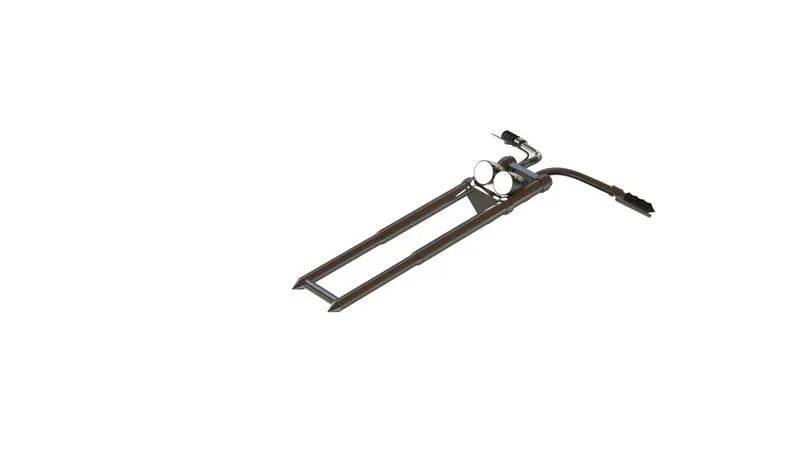
10. front fork: It is used to guide the entire vehicle. It holds the front wheel and other necessary levers.
Create a long tube on the front plane by creating the necessary sketches using lines and dimensions. use the revolve feature and revolve extrude the base sketch. Then on the top plane create the base sketch for triple clamps using appropriate dimensions and sketches. use a linear pattern for populating the clamp, also at the bottom end create a sketch for axel and extrude it according to dimensions. Again on the front plane create a base sketch for the headlights then use revolve extrude feature to make the base headlight body. In order to make handles, we would need multiple curve sketches so that we can use the projected curve feature. Select the front plane and make a sketch using the spline and make another sketch on a right plane using spline use projected curve feature. Use the sweep pattern to make handlebars. the same process is used for the brake wires. use mirror feature and mirror the bodies. By using combine feature make required bodies into a single part. Lastly, apply the required appearance material to each part.
Features: extruded boss/base,revolved boss/base,extruded cut,revolved cut,project curves,swept boss/base, dome,combine,mirror,chamfer,fillet
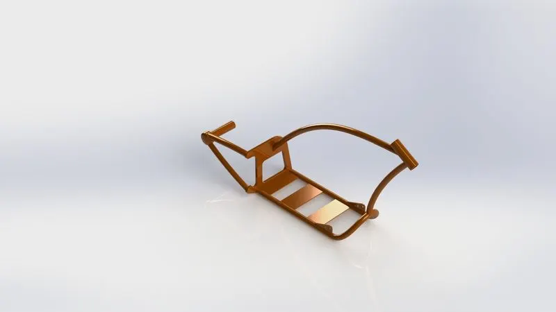
11.Chassis: It is the frame body of the vehicle to which every part are attached and also it provides support to those parts
Initially, the blueprint of the chopper is inserted into Solidworks on the front plane and its location and transparency are adjusted according to need. Blueprint is used as a reference sketch for the overall shape of the design. By using splines, lines and given dimensions basic sketch is created. features like revolve, extrude boss/base, split, sweep, linear pattern, extruded cut, revolve, cut, dome, combine, mirror, Chamfers and fillets are used for creating a solid body of chassis. These are connected with a plate at the back of the chassis.
Features: extruded boss/base,revolved boss/base, linear pattern ,extruded cut, revolved cut, project curves, swept boss/base ,dome ,combine , mirror ,chamfer ,fillets
12. Engine: It is the component of a vehicle where power is generated by the combustion process and is then transmitted to wheels for motion.
Initially insert the chopper blueprint onto the front plane and then adjust the blueprint parameters according to the need. The base of the engine block is created on the front plain using 3 point arc and lines and are connected using tangent relation .extrude the sketch using the given dimension. Again select the same base sketch and extrude the circles only up to given dimensions. select front plane makes another sketch which will be the backside of the engine block. select the right plane and make a sketch of pulley use revolve extrude function. repeat the same process to get a total of 2 pulleys. make a cylindrical part on the front plane next to the engine block and then extrude boss/base sketch. make a reference line sketch on the front plane which shows the twin-engine block lengths. At the end of this sketch make a reference plane and on that plane again sketch the upper end of the engine block. Extrude this sketch on both sides separately based on dimensions. make a sketch for radiator and extrude cut it then use the linear pattern function to populate it over twin-engine blocks. Create a circular sketch and use curves for silencers on both front plane and right plane and then use the projected curve function to make a common profile out of it. use swept boss function to make a solid body. spark plugs are created at the end. Apply appropriate appearance to it.
Features: extruded boss/base ,revolved boss/base ,extruded cut ,revolved cut ,circular pattern ,project curves ,swept boss/base , dome ,combine ,mirror ,chamfer, fillet
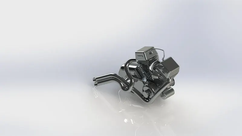
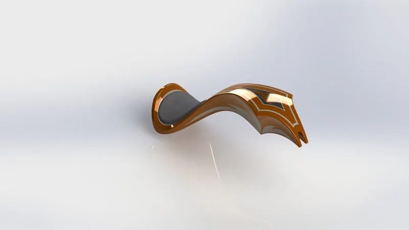
13.Gas/fuel tank: It is the fuel storing component of a vehicle which provide fuel for working the engine.
On the front plane make a sketch using splines, construction lines and then use projected curves to create half of the tank. Use features like loft surface and boundary surface to make a smooth curvy surface. Create another surface sketch in order to create a seat. use surface extrude feature and the use mirror feature to mirror everything remember to knit the entire surface together. Apply appropriate materials on the gas tank and seat
Features: swept surface, loft surface, boundary surface, project curves, knit surface, sweep cut, combine, steel, mirror and fillet
14.Assembly: Flow chart
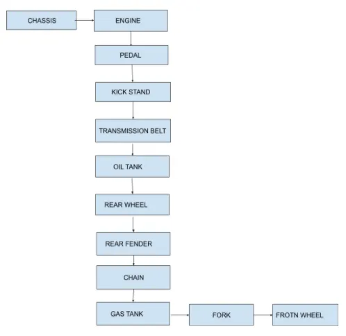
All the designed components are taken into the assemblies section in Solidworks and using appropriate mating features such as concentric, coincident, parallel, etc the entire assembly of American chopper is created. After assembly decals are applied to the chopper
- mirror feature is used to mirror the pedal onto the other side of the chopper model
The assembled model is then taken into Solidworks visualize or using photo-view 360 final renders are produced
Rendered images:
1 final render in Solidworks visualize
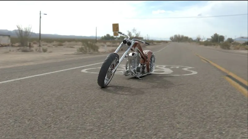
2.camera view (photoview 360)
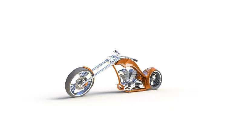
3.isometric view (photo view 360)
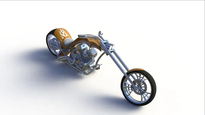
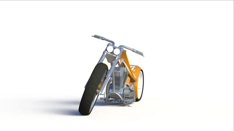
4.front view (photo view 360)
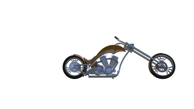
5.side view (photo view 360)
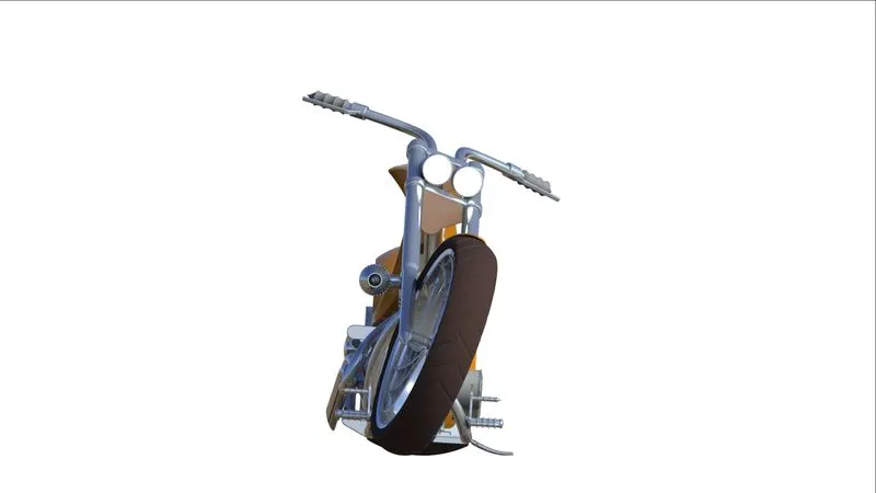
6.top view (photo view 360)
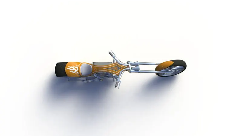
7.Viewport view (photoview 360)
Conclusion: Assembly of the chopper was done