Hood design-Week 2
OBJECTIVE :
To design the inner panel of the hood or the bonnet BIW of the car, according to the given master section and the necessary design precautions.
INTRODUCTION :
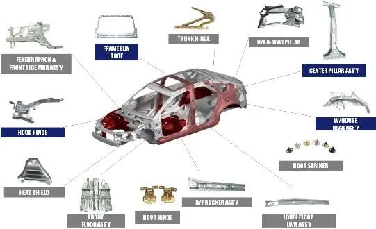
Hood/bonnet is the engine cover along with other parts, hinged generally to the front side of the automobile. The placement of the hood differs sometimes as some sports cars have their engine compartment at the back and thereby the hood is placed at the back of those particular cars. Hood is made aerodynamic in shape to reduce air effect and used to stylize the car’s front end
A concealed latch is typically used to hold down the hood
BIW or BODY IN WHITE :
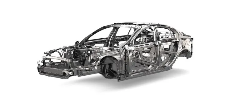
Is a stage in automobile manufacturing in which a car body’s frame has been joined together, that is before painting and before the motor, chassis, and final assembly. assembly involves different techniques such as welding that can either be spot, MIG/MAG, riveting, clinching, binding and laser brazing. The term derives from the manufacturing practices before steel unibody Monique when automobile bodies were made by outside sources on separate chassis on which engine fenders were attached.
PURPOSE OF HOOD DESIGN :
- Safety of the passenger
- Covers all engine, radiator, and other necessary components
- Reduce air effect due to its aerodynamic shape design
- Reduce engine noise which helps for a quieter drive
- Provide access to engine maintenance
- Absorbs most of the impact forces when a frontal crash occurs
HOOD COMPONENTS :
- HOOD OUTER PANEL
- HOOD INNER PANEL
- LATCH & STRIKER REINFORCEMENT
- HINGE REINFORCEMENT
- STIFFENER PAD
- HINGE
DESIGN METHODOLOGY
DESIGNING THE HOOD WITH REQUIREMENTS :
- Inner panel thickness =0.75
- Outer panel thickness =0.75
- Reinforcement thickness =1.2mm
- No sharp corners inside the components
- No negative drafts as it is harder to manufacture such parts
- Small emboss should not exceed the maximum depth of 6 mm
- Provide corner reliefs
- Provide mastic points to reduce NVH
STUDY ON WAD (WRAP AROUND DISTANCE )
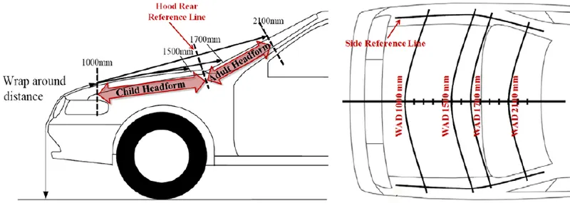
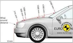
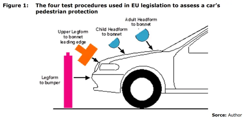
During most pedestrian-vehicle crashes the car front impacts the pedestrian and the whole body wraps around the front shape of the car. This influences the head impact on the vehicle. Meanwhile, the windscreen is a major impact point and tested in NCAP conditions. The severity of injuries is influenced by car impact speed; type of vehicle; stiffness and shape of the vehicle; nature of the front (such as the bumper height, bonnet height, and length, windscreen frame); age and body height of the pedestrian; and standing position of the pedestrian relative to the vehicle front. The so-called Wrap Around Distance WAD is one of the important measurements for the assessment of the protection of pedestrians and of bicyclists as well because the kinematic of bicyclists is similar to that of pedestrians.
For this study accidents of GIDAS were used to identify the importance of WAD for the resulting head injury severity of pedestrians and bicyclists. GIDAS (German In-Depth-Accident-Study) collects accidents as a representative sample of the German accident situation based on in-depth-investigation. A total number of n=548 pedestrians and n=436 bicyclists suffered a head impact with the car collected within n=27,666 accidents with all kinds of traffic participants and injured persons from the years 1999 to 2013 which are used for the study.
Results: A significant influence respectively an increase of WAD by the driving speed of the bicycle cannot be found. The cumulative frequencies show that WAD 1500 only covers about 8% of bicyclists but 18% of pedestrians. WAD 2100 covers about 51% of bicyclists and 74% of pedestrians. The WAD for pedestrians as a measure of distance from the ground to the impact point of the head is dependent on the impact speed of the car. For lower speeds, the front hood area is more often contacted, and for higher speeds the windscreen. For Vans and off-road cars, front hood impacts can only be seen in lower-speed collisions. The WAD of bicyclists, in general, is higher than for pedestrians. The cumulative frequencies of body heights show that bicyclists are larger than pedestrians. The injury severity of the head (AIS head) is increasing with the age of the pedestrian or bicyclist. Only 6.9% of pedestrians and 3.3% of bicyclists in the age group of 16 to 25 years suffer head injuries of AIS 3+, in the age group over 55 years there are 19.7% of pedestrians and 16.1% of bicyclists.
The WAD is not a significant influence parameter for the injury severity of the head. The WAD is only increasing slightly with higher injury severity of the head (AIS head). The WAD is a useful parameter for the correlating impact speed of the car. Age and impact speed of the car has a highly significant influence (p<0.001) and body height has a slightly significant influence on the injury severity of the head (p<0.05).
SHEET METAL OPERATIONS :
- Blanking and piercing
- Deep drawing
- Embossing
- Hemming
BLANKING AND PIERCING :
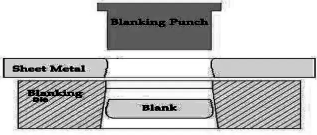
In the blanking, piercing, and shearing process a punch and die are used to modify webs. The tooling and process between the two are the same, only the terminology is different. In blanking the punched-out piece is used and called blank whereas in piercing the punched-out piece is scrap. The process for parts manufacturing simultaneously with both techniques is often termed pierce and blank, an alternative of piercing is punching.
Pros
- Reduces the bodyweight
- Improves the strength of the body
- Distributes the impact forces
DEEP DRAWING :
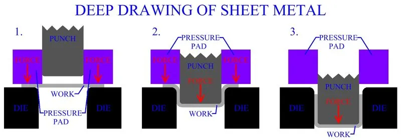
Deep drawing of sheet metal is used to form objects with depths. It is plastic deformation in which a flat sheet metal or plate is formed into a recessed 3-D part with depth several times the thickness of metal. In this sheet, a metal blank is radially drawn into a forming die by the mechanical action of a punch. It is thus a shape transformation process with material retention. The material used is generally aluminum as it can absorb twice the crash energy as of mild-steel while keeping the overall weight lower than mild-steel
Pros
- It is a very cost-effective method of producing various types of individual parts which are seamless products
- Faster cycle times
EMBOSSING :
Sheet metal embossing is a stamping process for producing raised or sunken designs or relief in sheet metal This process can be made by means of matched male and female roller dies or by passing sheet or a strip of metal between rolls of the desired pattern.
It is done by pressing a sheet into a female die which has a design attached to it. this is usually done with a male counterpart underneath the paper so that the two and design is transferred to the sheet
Pros
- Embossing enables us to highlight the important elements of the products
- Transfers even the finest details
- Permanent design that lasts forever
HEMMING :
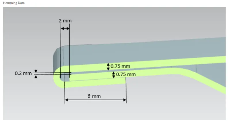
Hemming is a sheet metal forming process in which sheets are joined by bending them to 180 degrees. Automotive body panels and automotive parts such as deck-lids, doors, hoods, and tailgates are formed by the hemming process, in this process usually, a sheet is bent with the help of the inner and outer sheets. hemming is formed in which the edge of the sheet is folded over another parting to achieve a tight fit.
Pros
- To fasten two sheet metal parts by folding the edge of the sheet back on itself.
Types of hemming
- Rolled hemming
- Closed hemming
- Teared drop hemming
- Open hemming
APPROACH: TOP-DOWN :
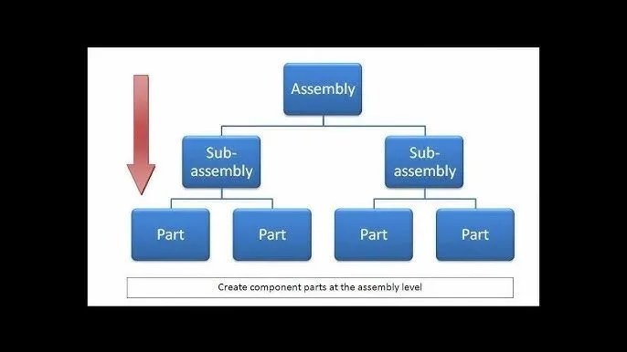
in the top-down approach, you have to create the blank assembly first and then you have to go on creating the subassemblies and parts in it. So, if the main assembly is at the topmost level and the components are on the bottom-most level, then you are coming from top to bottom and it’s top-down assembly.
DESIGNING OF COMPONENTS :
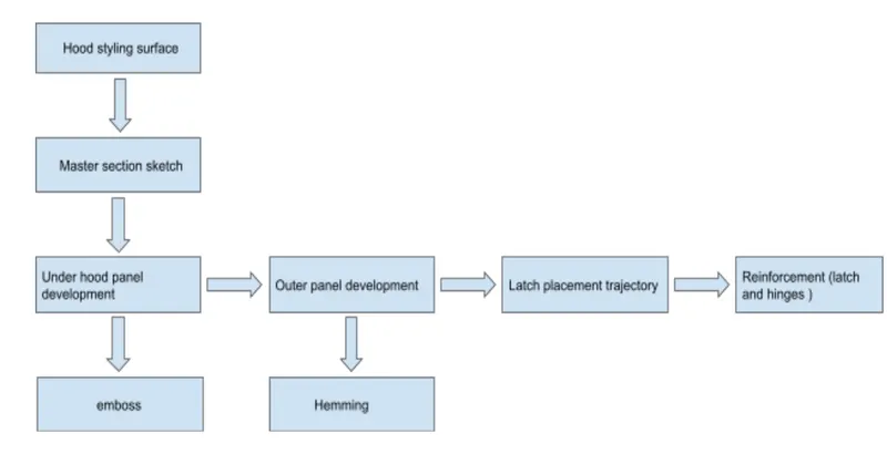
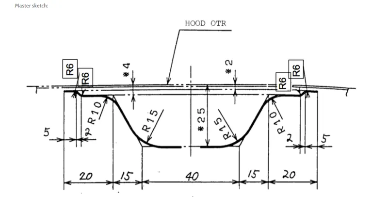
MASTER SKETCH:
- The master section is created based on the requirement received from the stylize team and the manufacturing requirements.
HOOD ASSEMBLY :
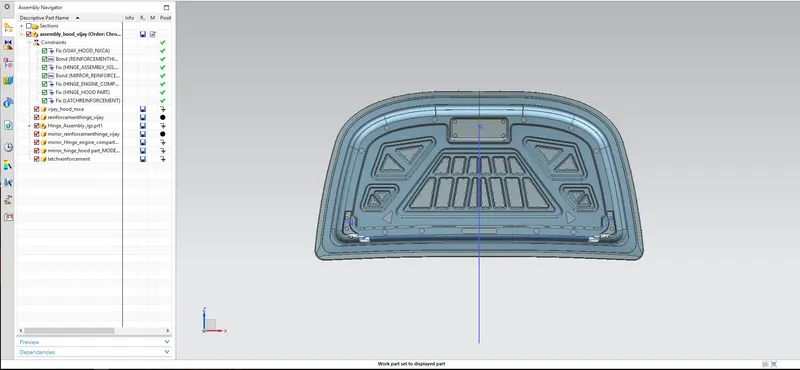
- An initial data file of the outer hood surface is received from the styling team
- Then by keeping it as a parent file two work surfaces were created and named separately as hood inner panel and hood outer panel
- Then in the assembly navigator, a new assembly was created and the other parts were added in
- Lastly, after creating both inner and outer hoof panel hinge assembly and latch will be constrained
HOOD INNER PANEL :
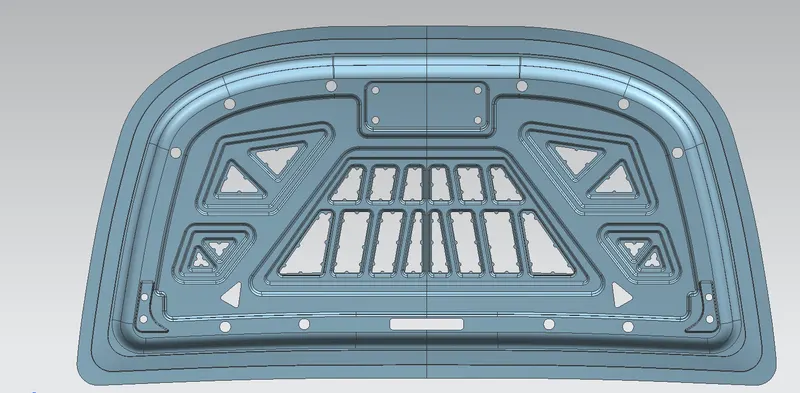
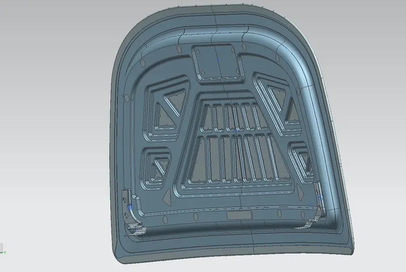
- After getting the styling surface it is trimmed in half using the trim surface along the x-coordinate plane
- Then two surface were extracted at a distance of 0mm and then one group is named as parent file and the other one is used as the working surface
- By using the master sketch three surfaces were off-set at a distance of 2mm, 4mm and 25 mm from the working surface in a downward direction
- For creating the 5mm flange the corner of the tangent curve will be offset inwards at a distance of 20 mm with a corner fillet of 30 mm and trim out the remaining surface
- Then for creating the next flange the second offset surface was trimmed at a distance of 40 mm
- By using the through curve feature both flange surfaces were joined together with an outward angle of 80 degrees as per manufacturing constraints
- Then again a third flange is created at a distance of 55 mm
- Then required embosses were created to reduce the disperse the transmission of force also emboss must have an outward draft for easy manufacturing
- Then by using features like edge blend and face blend sharp corners were smoothened and blended out as per the manufacturing requirements
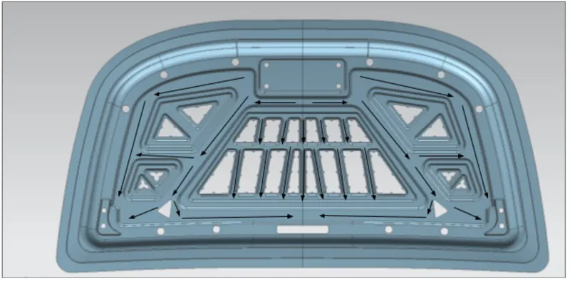
FORCE DISTRIBUTION
Black lines represent force propagation in case of an accident
- For fixing the hinge assembly a flat-surfaced emboss was created.
- Before mirroring the panel surface the surface was extended and then trimmed and then mirror command was used to mirror the panel
- Both panel surfaces were joined together with each other by using sew command and then finally a thickness of 0.75 mm was added to the panel and the inner panel was created
MASTIC SEALANT :
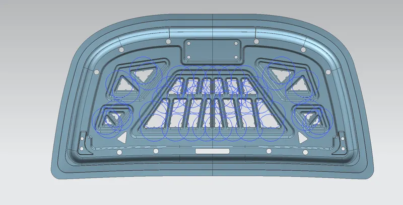
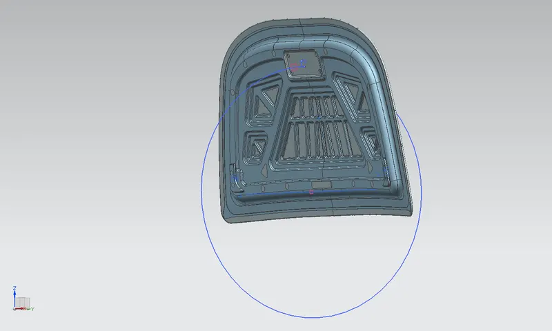
It is an elastic compound that behaves like a rubber compound. The mastic points are defined on the hood inner panel where the hood can easily deform. they help the hood outer panel to come back to its original shape after it gets deformed. The mastic seal has an effective area of 80 mm while creating emboss a coin-shaped extends was created for applying the mastic points. The mastic points will help the inner panel be fixed with the outer panel.
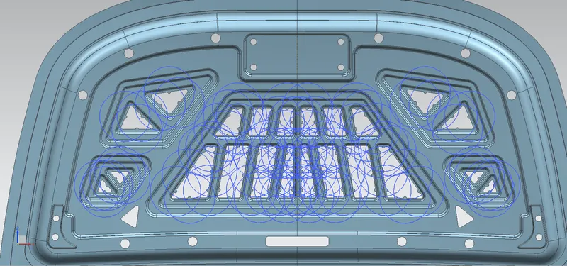
There is another function of the mastic seal which plays a major role in reducing the noise, vibration, and harshness (NVH) created in the hood. providing a higher number of mastic seal points ensures a higher reduction of NVH.
Notes; the blue circle represents some of the mastic sealant points on the hood with a coverage dia of 80 mm. (only shows some of the points for clear visibility )
The below image shows all the mastic points being represented by blue circles
HOOD OUTER PANEL
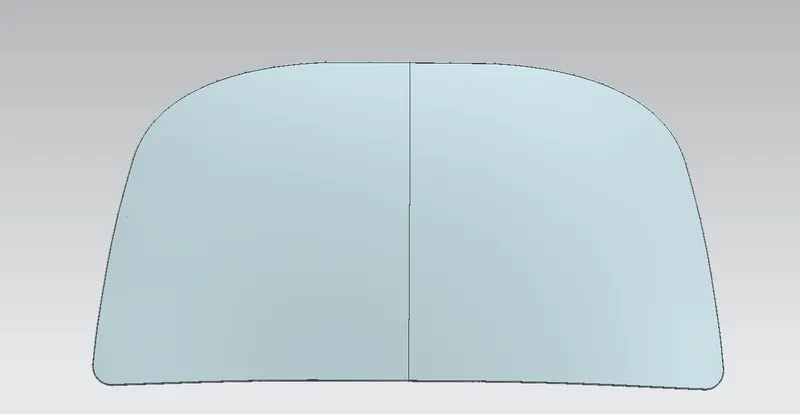
- The outer panel of the hood was created by creating an offset surface from the styling surface and the trimmed to half then for creating hem flange about 6mm around the outer panel for creating the hold with inner panel
- Law extension was used on the outside curve and the generated surface was offset to 6mm and the remaining surface was trimmed
- By using the face blend the hem flange was created
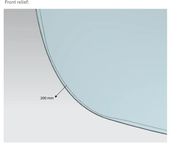
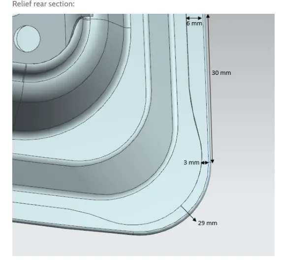
- Now by using the curve on the required corners relief was provided on the top and bottom corners as a requirement
- the other half was mirrored and sewed together
Hemming data :
Front relief data
Relief rear section
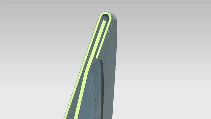
Cross-sectional view of the hood
POSITION OF THE HINGE ASSEMBLY
- The hinge was positioned by applying the required constraints in the assembly
- First hinges were placed at required positions using move constraints and then fix constraint was applied.
- The back surface on the hinge hood part is to touch with the emboss part on the panel for the hinge placement
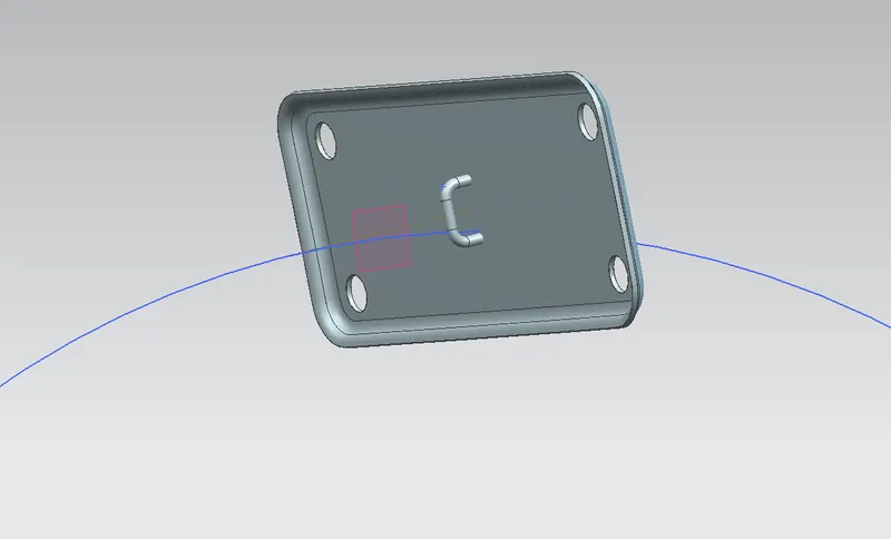
POSITION OF THE LATCH AND STRIKER
- First, the latches were positioned roughly using the constraints
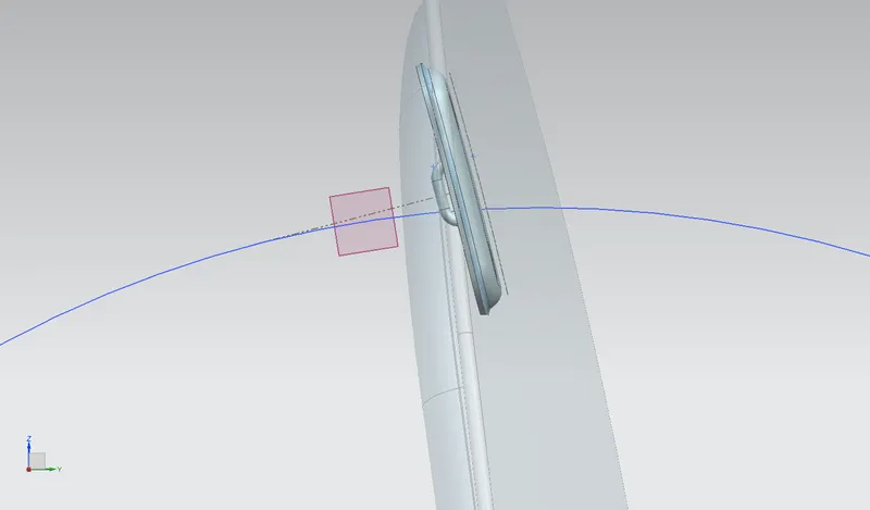
- By using studio spline a spline was created which acts as an axis for the latch placement
- A datum was created at the center of the spline and then a circle was created which touches nearly at the center of the latch reinforcement this circle is what represents the trajectory of hood closure
- A line was projected onto the reinforcement of the latch from under the panel
- Then a line was created which is both tangential to the hood trajectory as well as the projected curve on reinforcement
- With the help of necessary sketches latch was created
Reinforcement (hinge and latch )
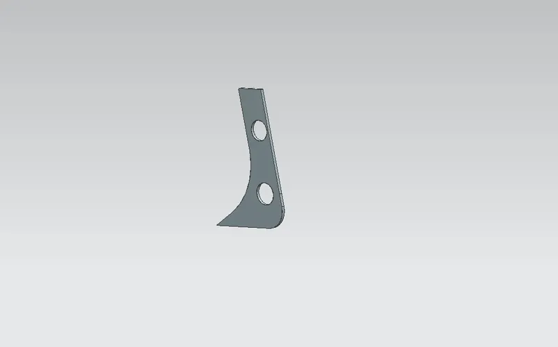
- These were created using wave geometry linker, project curve, through curve, trim sheet, and thicken features
CONCLUSION :
Finally biw of a car hood was designed as per the industrial manufacturing requirements