Week 8 - Challenge 3 - Switch Bezel Design
DOOR SWITCH BEZEL DESIGN
Objectives:
- To analyze the given class A surface and define possible tooling axis for molding process.
- To Generate class B, class C surfaces by offsetting and make a thickened solid part
- To conduct draft analysis
Software used: DS CATIA P3 V5 - GENERATIVE SHAPE DESIGN, PART DESIGN WORKBENCHES
Introduction:
Switch bezel is one of the main aesthetic surface in an automotive door panel. The simplified surface patches are given for the project to generate solid part. I use the offsetting method to generate class B surface and sweep for class C surfaces. Later we will make a proper tooling axis feasible to all surface patches. C surfaces should be made with a proper draft angle to ensure the moldability of part. For that purpose, we use draft analysis.
Design methodology/approach:
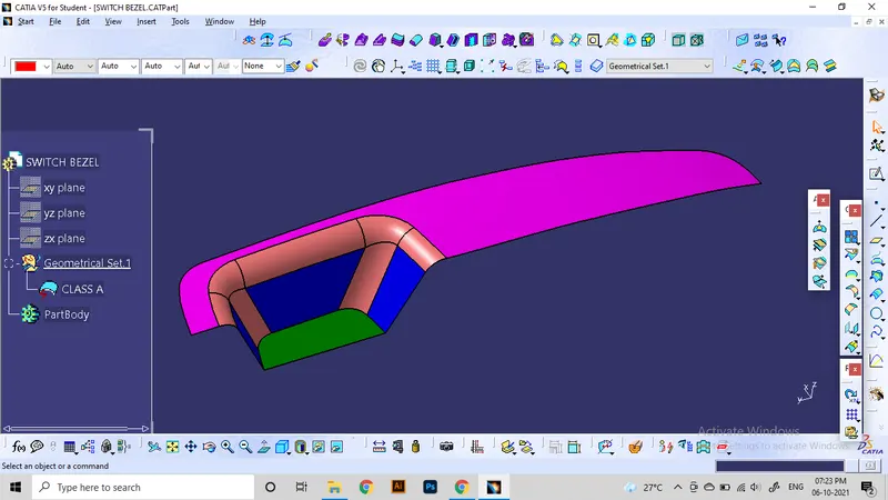
The given simplified class A part is shown below. Different types of surface patches are marked with different colors.
Step 1: Tooling axis definition
Since the shape is irregular in all direction, it's not possible to find a symmetrical shape on the surface. We need to assume a line of axis that's feasible enough to be functional. So I'm taking the lower base of the part as a plane which the tooling axis passes through. Assume a point at the middle of the base surface.
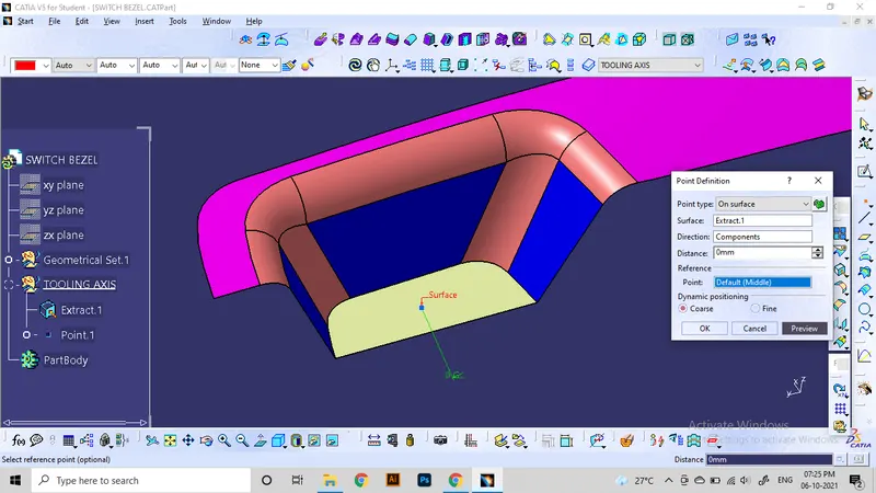
By taking the point as projection make an axis system around it to define planes. we will be using this plane to make sketches. First use the sketch in YZ plane. Using proper intersection of the class A part, we can determine the line which comes bisecting the two side surfaces in the yz plane.
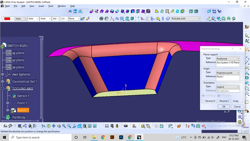
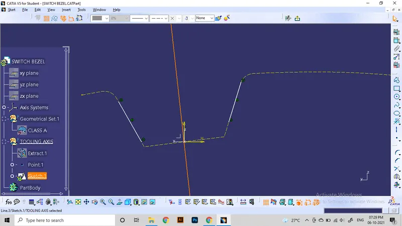

Next make sketch in ZX plane to assume a line which comes at a proper angle to the side surface as shown. here i'm taking 6 degrees.
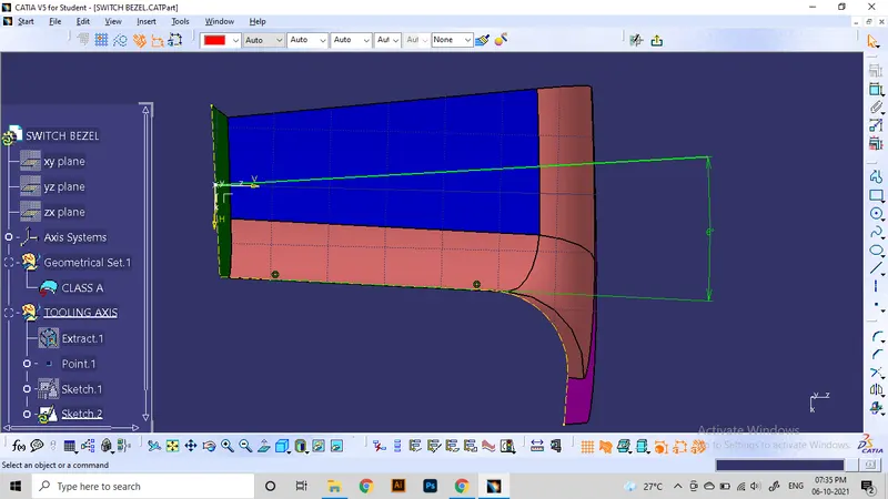
As the sketch output, We got two lines intersecting at one point. A tooling axis can be determined by bisecting these two.
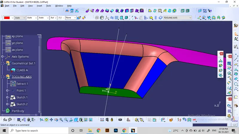
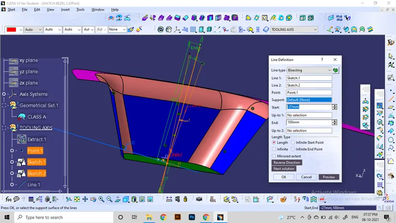
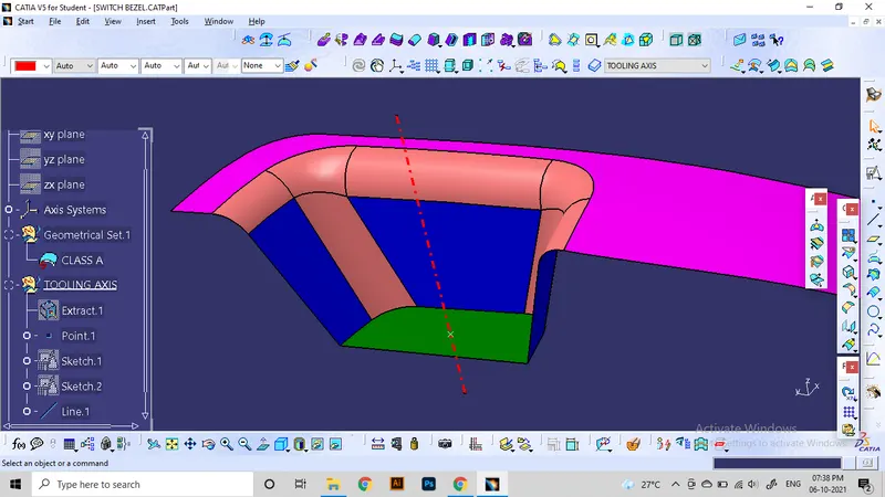
Step 2: Class B surface generation:
B surfaces are usually the offset parts of the A surface patches. But, in this case, the A surfaces include Complex surface forms and fillets which cannot be offset directly, So we need to get the parent patches which used to shape the class A part to offset class-A surfaces. We need to use Extraction, untrimming and extrapolation commands to make those surfaces.
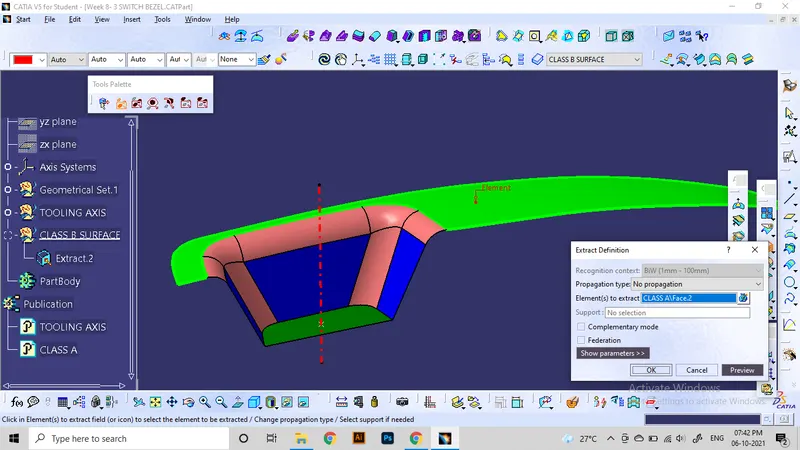
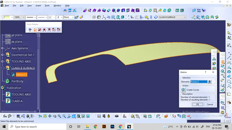
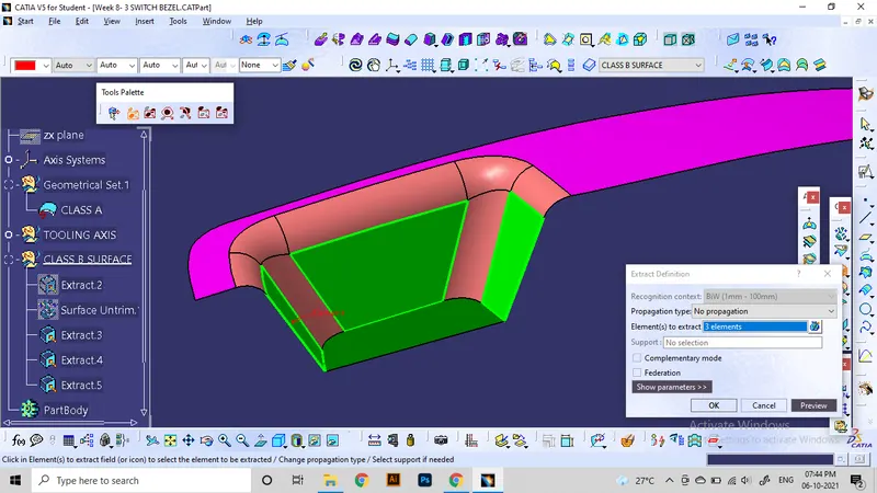
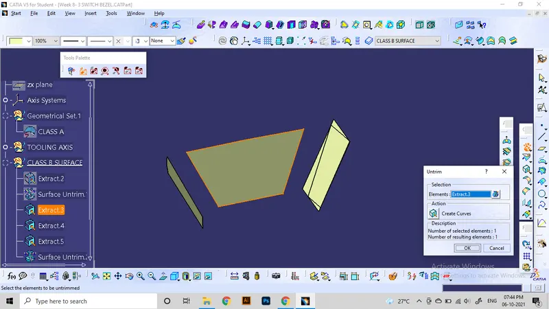
All surfaces needs to be extended enough to cross their edges to the nearby element.
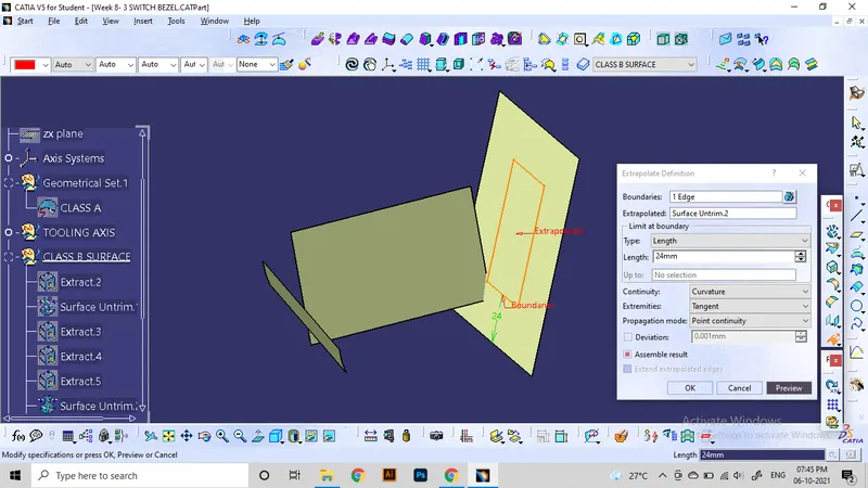
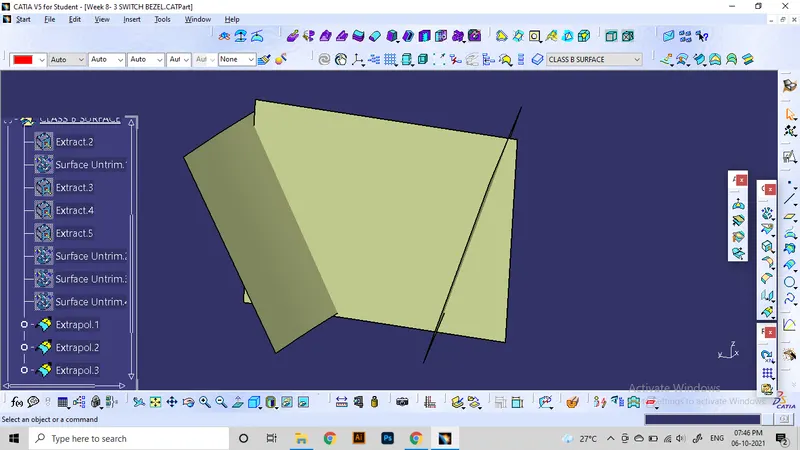
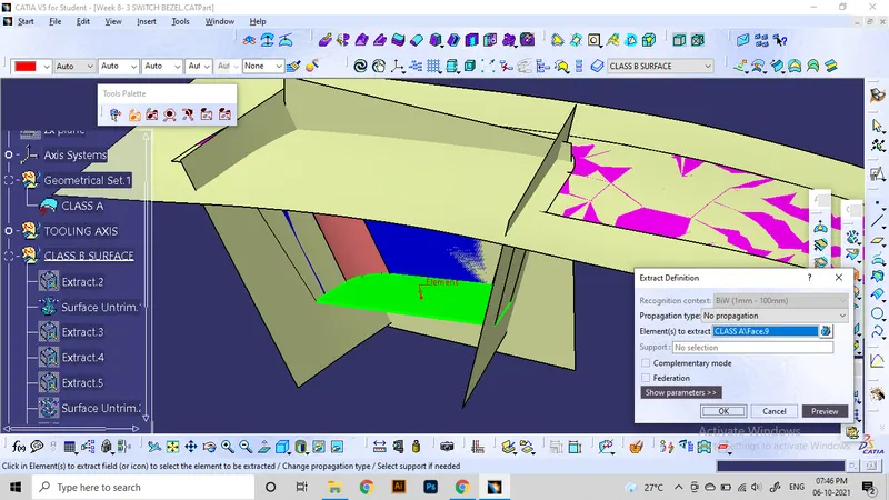
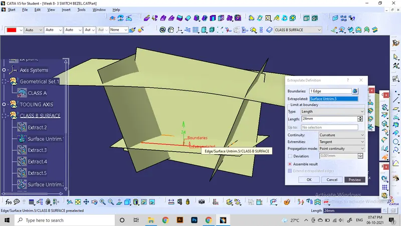
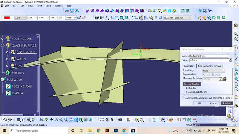
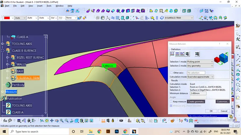
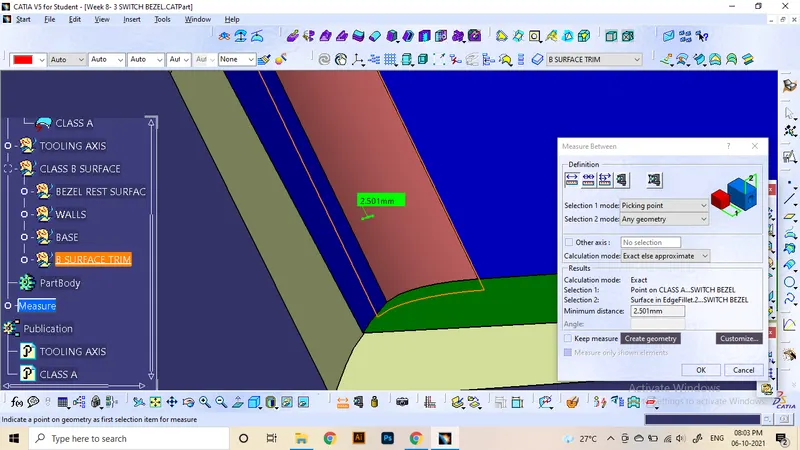
If all patches are ready as shown here, We can start offseting Those surfaces upto the thickness of part. Here it is taken as 2.5 mm.
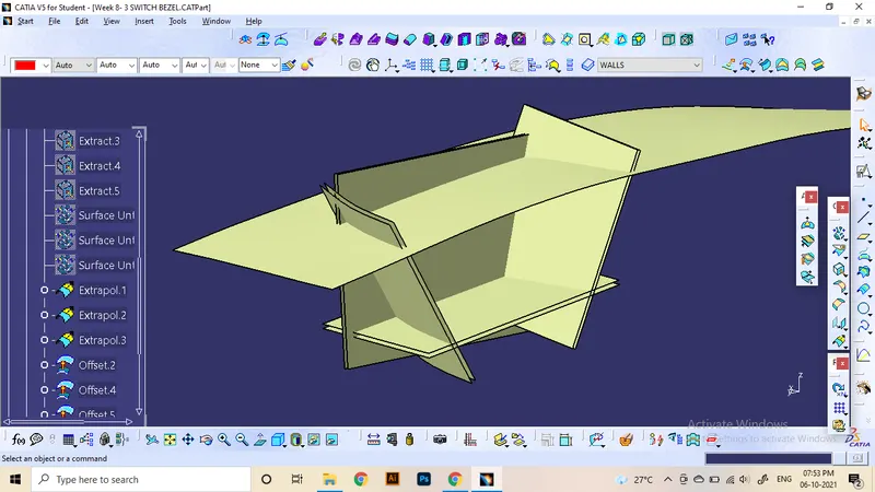
Later use trim command to remove excessive patches. make sure the proper surfaces are made in Show mode. otherwise the surface will intersect with class A failing to ensure thickness.
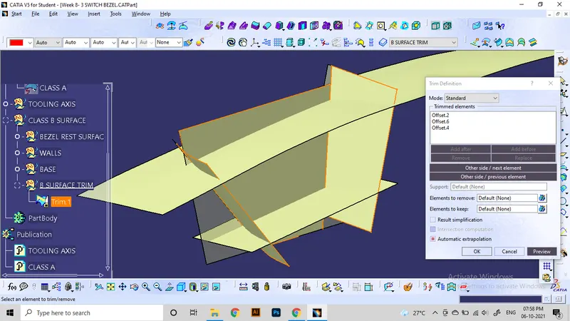
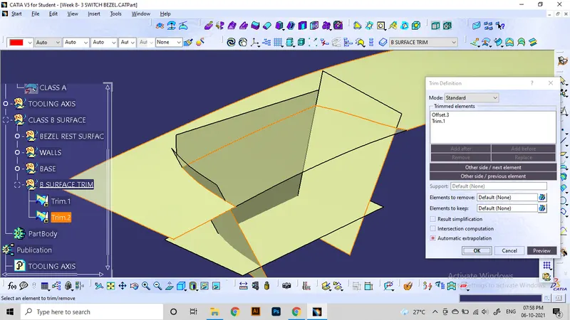
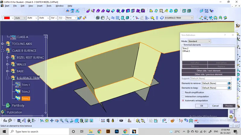
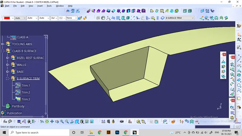
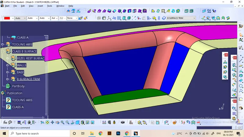
After that start to make the fillets at desired edges. Dimensions of fillets can be determined by calculating using the fillet radius of class A and the thickness of the part. Making sure that the Class B srface always comes at a constant thickness to the class A.
For the side surfaces, radius of fillets on class A is 15mm. so for class B, it's 15+2.5mm
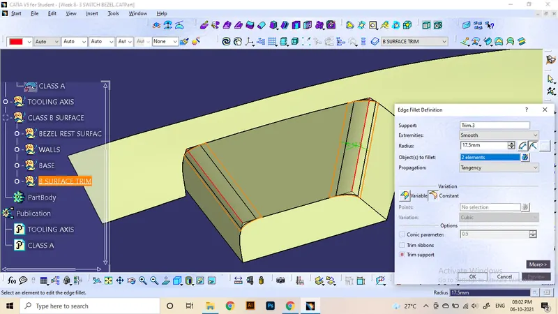
For top fillets, it's 14 for class A. so here it is 14-2.5 mm for class B, since the fillets will reduce radius at contracted surfaces.
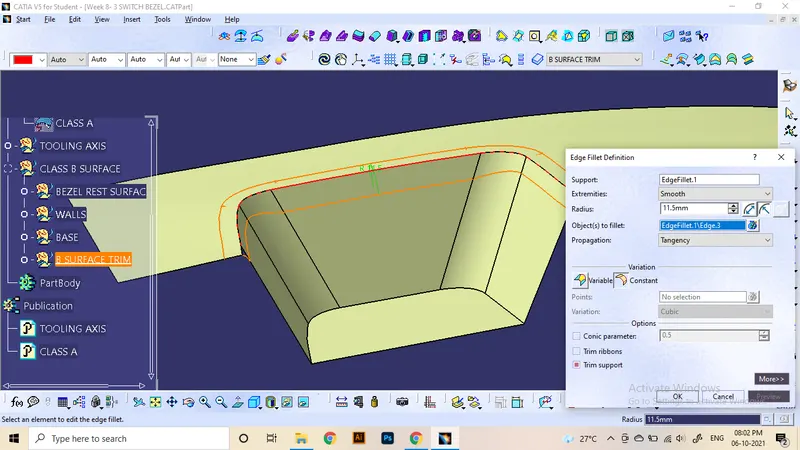
Measure the thickness at all regions using the measure command with picking point mode.
Step 3: Class C surface generation:
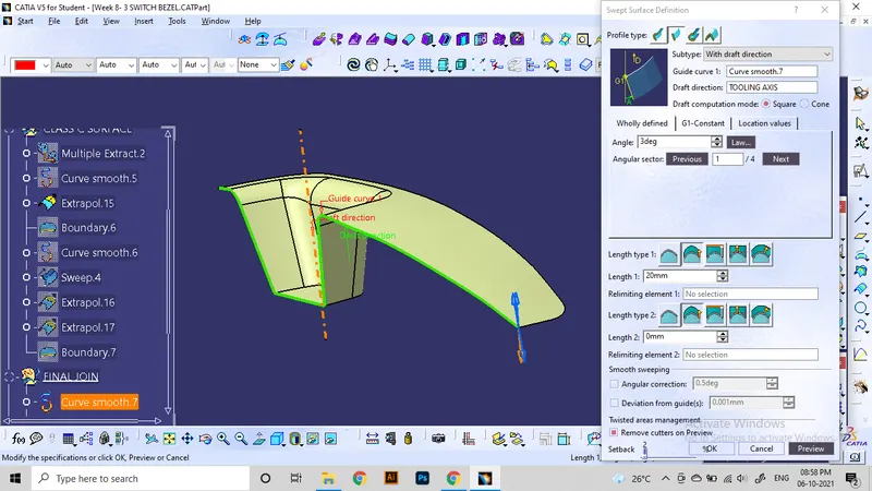
Here, the surface boundaries are forming a shape that is not suitable for sweeping directly. We need to define boundaries at specific areas and sweep them individually to make a proper C surface patch. hence i'm dividing the boundary into 2 set of curves using boundary command with limiting points.
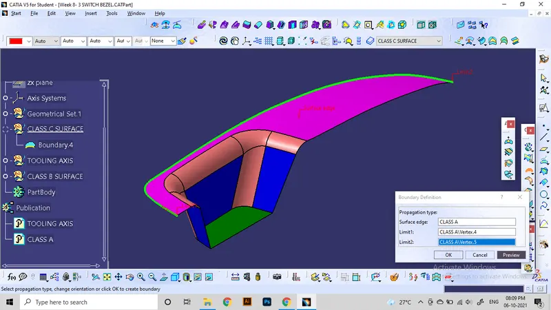
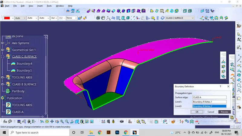
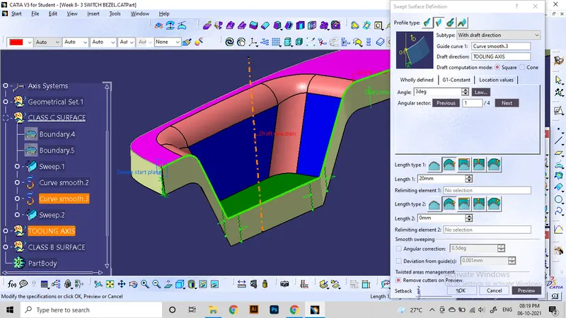
First, Sweep the boundary at one side with draft direction mode enabled. use tooling axis as draft direction and draft angle to be 3 mm as shown below. 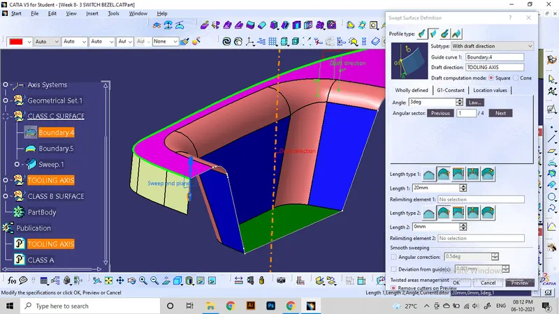
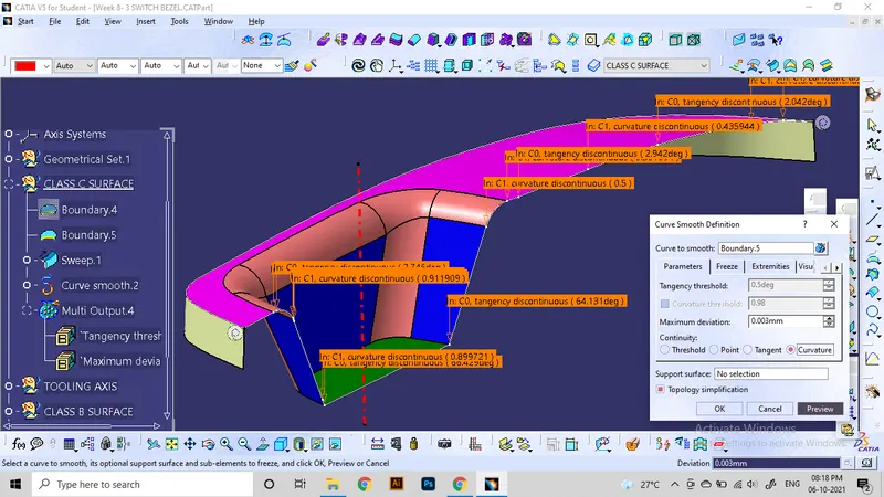
Here, we can see the drafted surfaces are not following proper continuity hence forming sharp edges on smooth areas. to avoid this, we need to smoothen the boundary line with smooth curve tool.
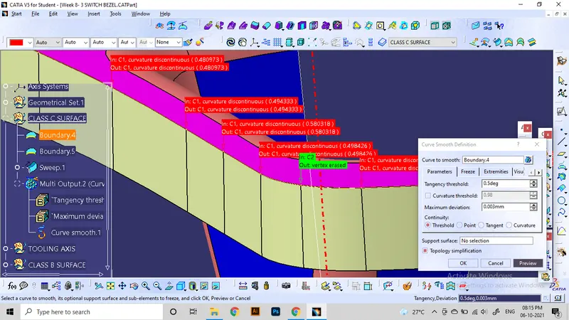
Then replace the boundary line which used for draft with this smooth curve. So the draft will get into this state. 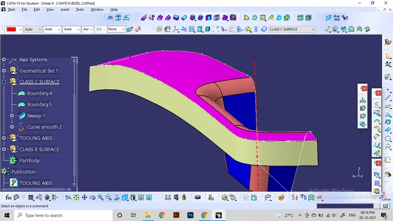
Similarly, make another draft for the next boundary line.
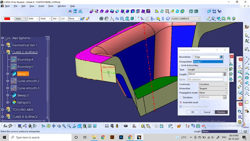
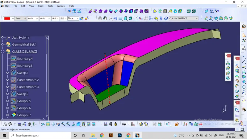
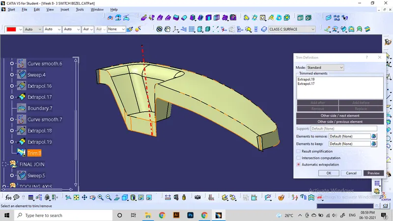
For connecting these drafted patches to one, extrapolate the edges of them to intersect with other and trim them into a single patch.
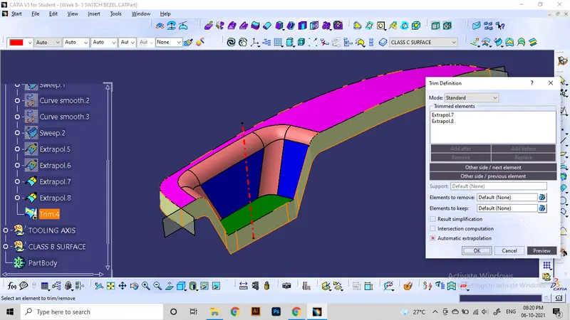
Step4: Finalizing the surface geometries
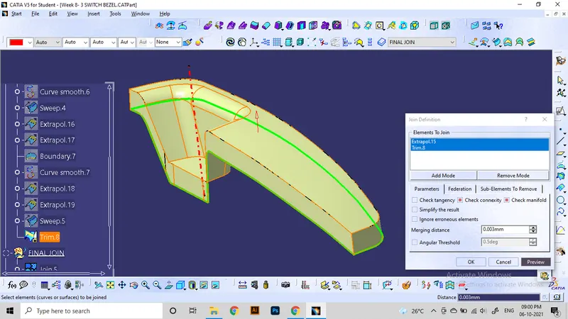
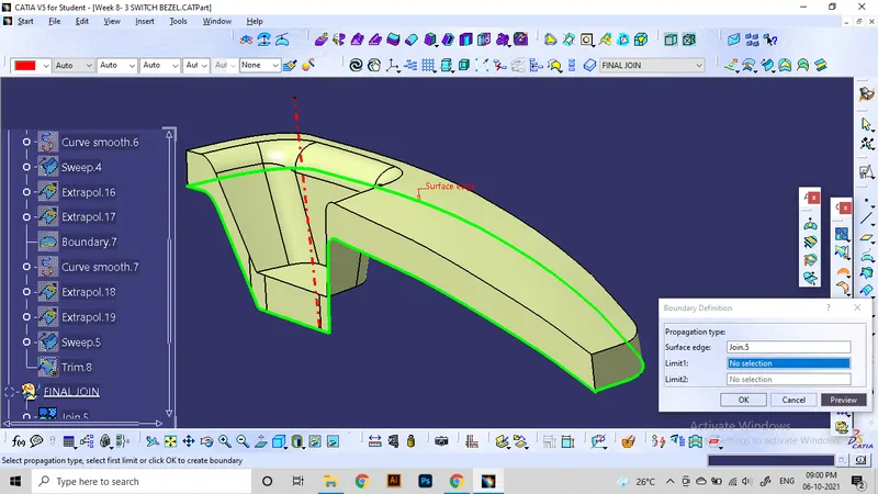
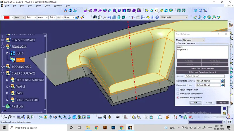
After preparing all 3 patches we can join the surfaces into single final patch. First join the Class A and C together. When joining, preview the edge formation to find errors or openings at the contact points. If the edges of two surfaces does not come in contact with the near edge, there will be an opening in the edge thereby forming a boundary area.
Since that will be a failure for solid part creation, all boundaries needs to be closed.
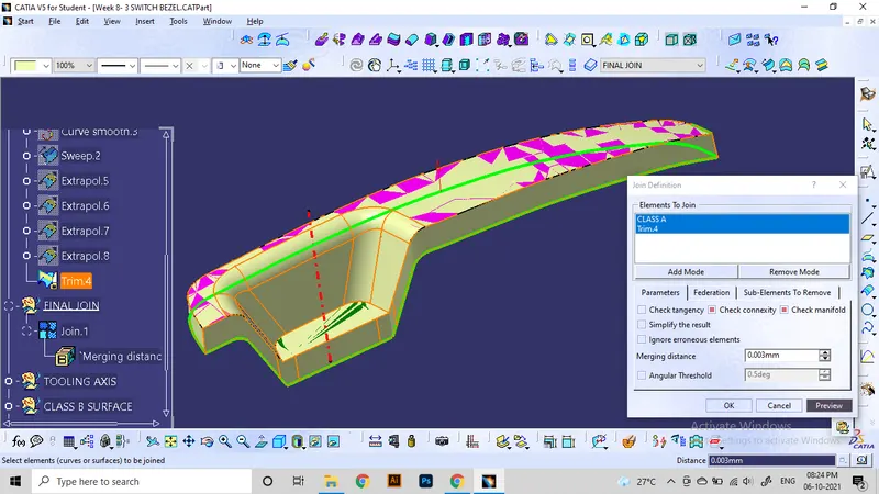
We can increase the merging distance when joining upto 0.003. That will add a slight tolerence to join, thereby closing most of the boundaries. For boundaries does'nt cleared after that, it needs to get extrapolated on the class A surface side and trim again with the class C surface leaving no boundaries. It may need to redo the processes for class C surface creation, or just modify only the required processes and local updating them.
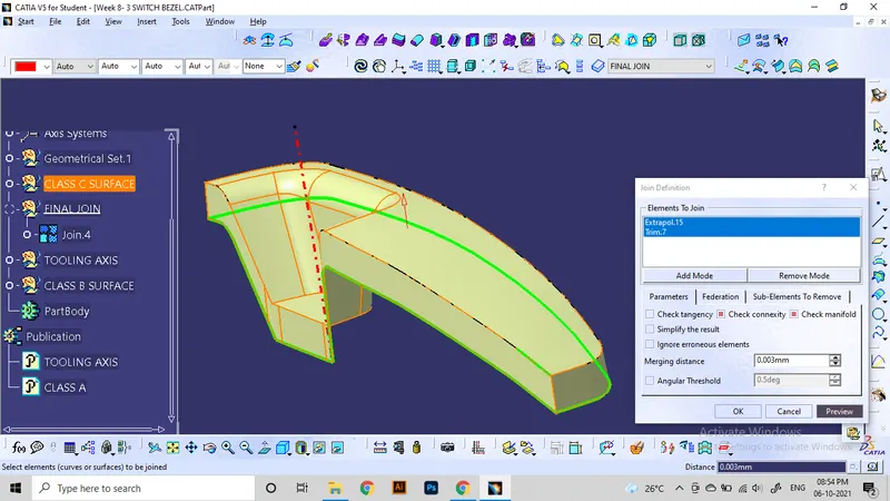
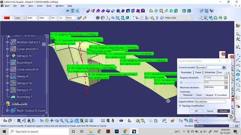
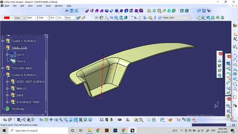
If the boundaries are closed successfully, trim the patch with Class B surface.
Step 5: making solid part from surface patches.
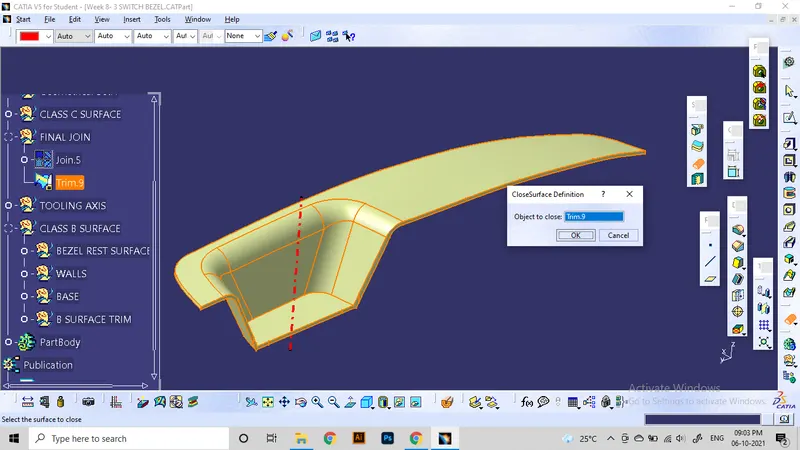
Move onto part workbench and make the solid body using closebody command.
Step 6: Draft analysis:
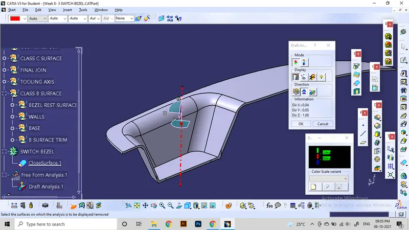
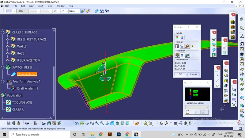
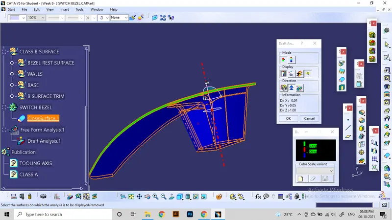
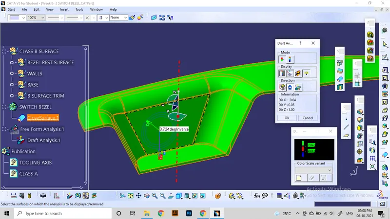
Using the feature draft analysis tool, analyze the class A and C surfaces for passing the draft angle check about tooling axis.
First it need to aling the compass on tooling axis, and click on the surface. Surfaces with more than 3 degree draft angle is acceptable for molding process. Here the analysis passes all surfaces as required.
Conclusion: Studied to generate Solid bodies from class A surfaces and their importance in functionality. Identified the types of errors that can be occurred during the process and the methods for re-adjusting them without major changes in forms. And to conduct Draft analysis on complex objects.