Week 8 - Challenge 3 - Switch Bezel Design
AIM:
To create the plastic component switch bezel using the class A surface and create the B surface for the class A and develop a final component.
OBJECTIVE:
Switch bezel with the feasibility of manufcaturing by ensuring the moulding conducts like determining the tooling direction, postive draft to the parallel profiles.
SOFTWARE USED: Catia V5
SWITCH BEZEL:
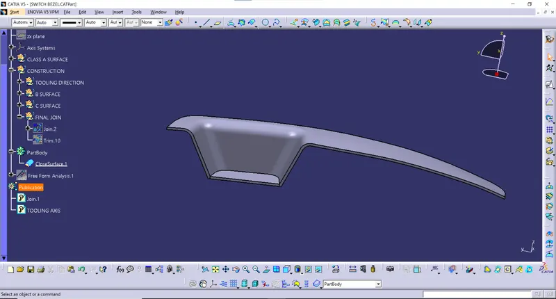
They are the components used to house the window pull up/down switches, along with the hand rest and holders. An example of which is shown below.
TOOLING DIRECTION:
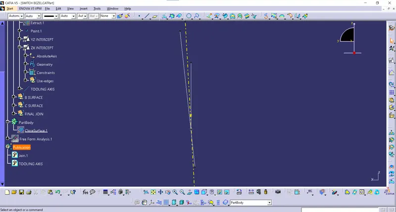
Initially the tooling direction has to be defined for the component in order to facilitate the creation and joining of the class A and the C surface creation. Also, tooling direction ensures the manufacturability of the component.
The base surface is extracted and the center point of the surface is created. Then the intercepts for the Y and X axis are taken as shown.
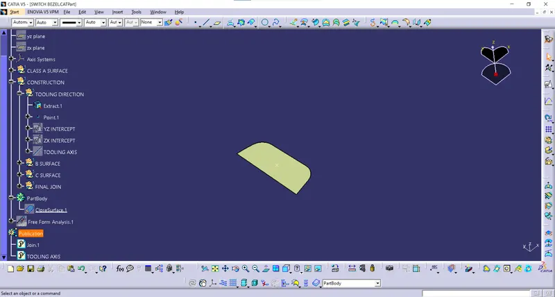
There is an intersection of the 3D elements made in the sketched part. Then the bisecting line is created by the point which created on the surface,
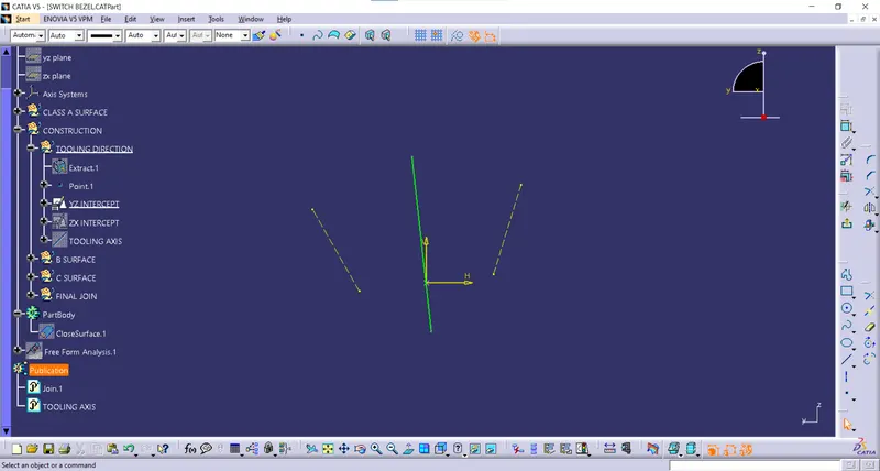
The same procedure is carried out for the X intersection too.
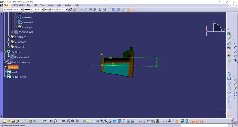
Then the tooling direction is created with the bisecting line between the two intersection lines.
B SURFACE CREATION:
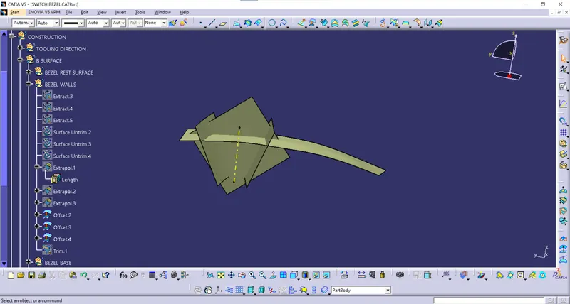
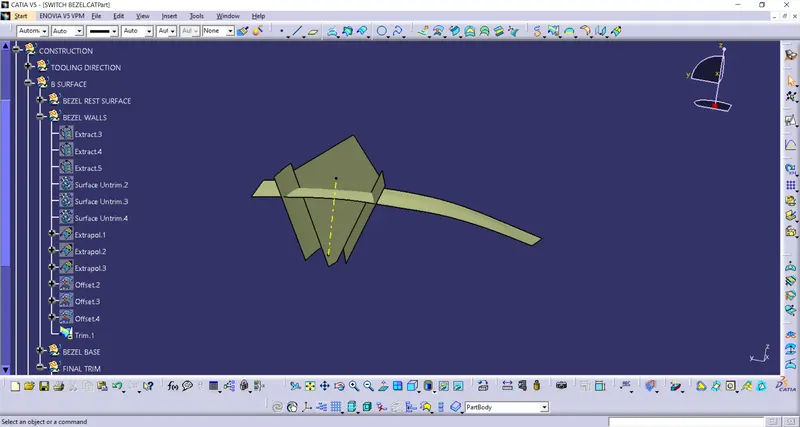
Bezel Walls:
Bezel rest surface
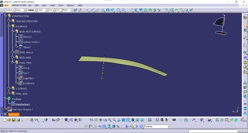
B surface trim
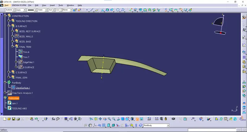
Fillet addition to the B surface
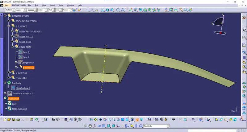
C SURFACE:
Carrying out the sweep operation with separate curves in order to overcome the tangential discontinuity.
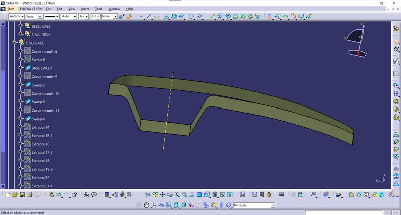
Trimming the separate sweep entities to form a single profile
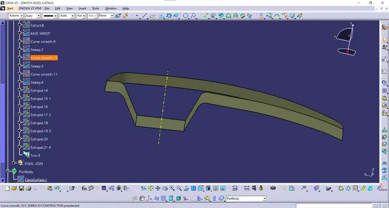
Joining the Class A surface and the C surface together.
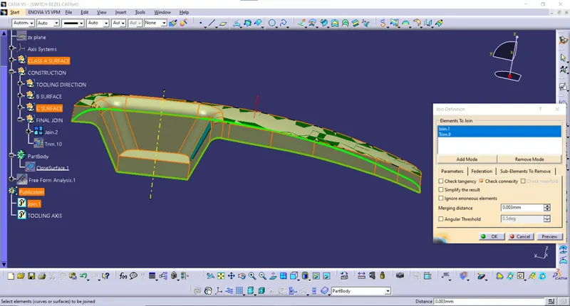
Trimming the joined surface with the B surface which finally gives the thickness for the component
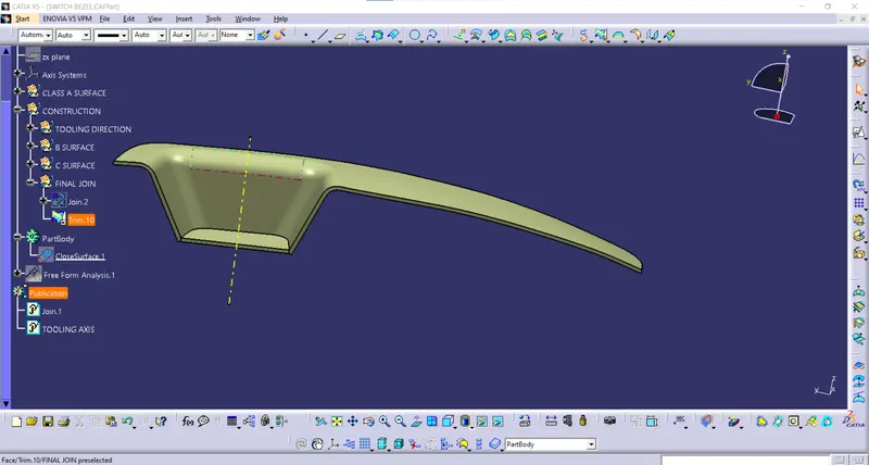
Giving the solid part model by closing the surfaces.