Week 8 - Challenge 3 - Switch Bezel Design
Switch Bezel Design
The First step is to join the different surface to form the class a surface and making sure there are no boundary or gaps. Once Class A is created it is published by the following steps Tools>Publication, this is done for easy access of the class a in the tree structure.
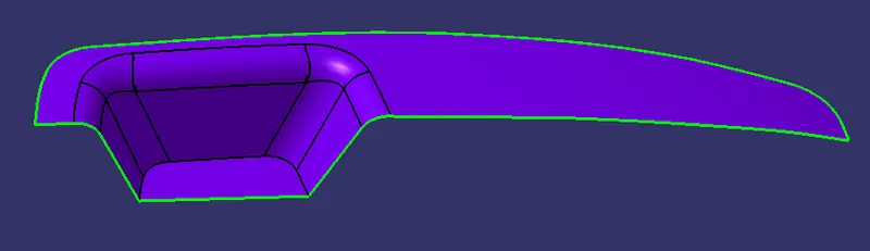
After the creation of class a tooling axis is created by the bisecting method. Intersection are created in the yz and xz planes respectively and seperate axes are created for the same, after bisecting the axes in planes using line command the correct tooling axis is created. Tooling axis is constructed in the z direction since it is able to clear almost all the sections of the class a.
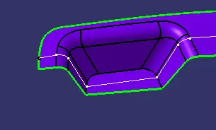
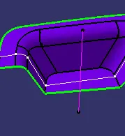
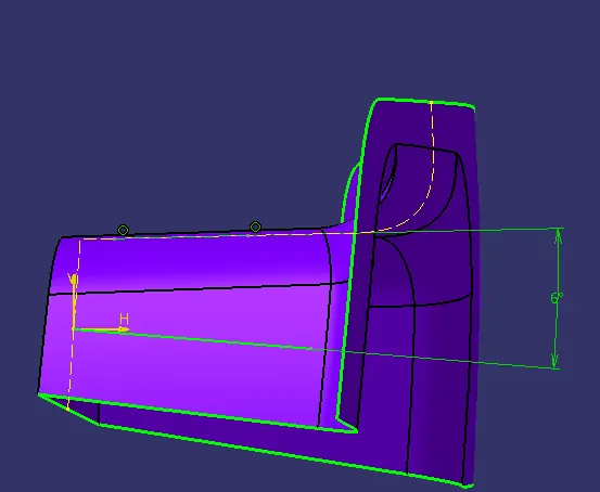
While creating the axis in the xz plane the xz axis is inclined at an angle of 6 deg from the intersection. 6 deg is provided to get better clearing for the wall of class a surface. After the tooling axis creation it is published in the tree structure.
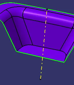
B surface creation can be approached in different sections and then finally trimming the required to form class b. Bexel rest, wall, Base are extracted from class and they are offseted to a distance of 2.5mm and the surfaces are extrapolated to be trimmed.
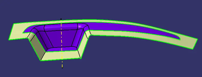
Surface highlighted in yellow is the class b surface. After creation they are published.
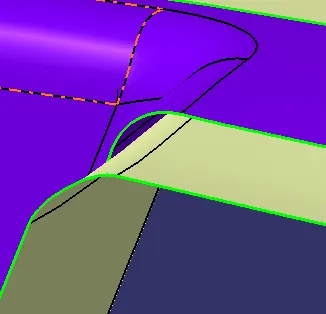 Edge fillet value is given as 12.5mm (15-2.5), 15 is the required fillet but taking in consideration of the offset value it is reduced to get accuracy around the edges.
Class C surafce is createdby extrating the boundary of the class a and smoothening the rough edges using smooth curve tool, once the boundary curve is obtained the surface are created using the sweep tool with selecting the option sweep with tooling axis and providing 3 deg draft. Surface high
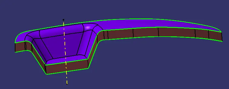
Final trim is obtained by trimming the Class A, B,C surfaces respectively.
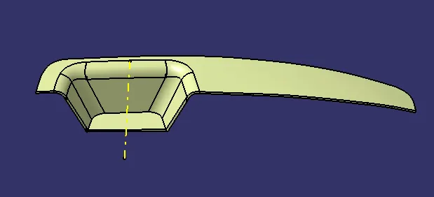
After forming the trim surface slect part tool and choose the close option to create the solid out of the trim surface.
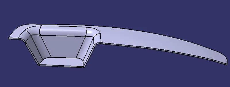
Draft Analysis on Switch Bezel:
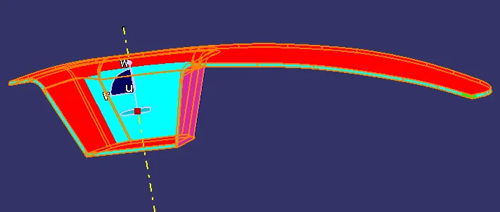
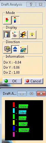
The View paramters is updated and the option Insert>Analysis>Feature draft analysis is selected to obtain the draft analysis dialogue box. The compass option is selected and it is dragged to the tooling axis once done it is locked, after this click on any area of the solid to obtain draft analysis.
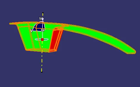
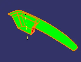
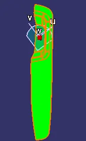
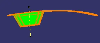
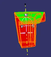
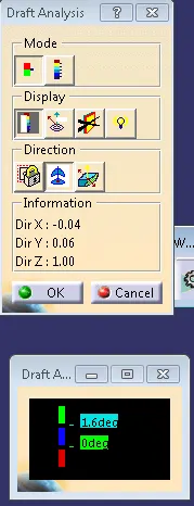
Draft angle is taken as 1.6 deg. the surface highlighted in red have the proovided draft angle. The are highlighted in red have negative draft.
Full Analysis mode is shown in the below image.