Week 8 - Challenge 3 - Coin Holder Design
Design of coin holder:
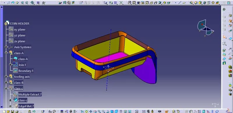
We need to create a coin holder of thickness 2.5mm with the given class-A surface. The class-A surface is shown in the below image.
Creation of class-B surface:
To create the class-B surface we need to have a tooling axis and also we need to check the draft analysis of the class-A surface.
To create the tooling axis, select the bottom face of the class-A surface and extract it. place a point on the surface. Using the point, insert an axis system and using the axis system and the point generate an intersection line of the class-A surface. After getting the intersection line, the angle between the extracted surface and the intersection line is found to be 90degrees. so, instead of using the bisecting method, directly we can create the tooling axis using the point and direction. once we have the tooling axis we need to check the draft analysis of the class-A surface. If the minimum 3deg draft angle is satisfied, then a class-B surface can be created.
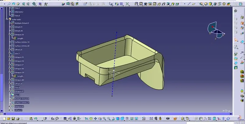
To create the class-B surface, we use commands namely, extract, untrim, extrapolate, trim and offset. Using these commands we extract the side walls, base, and top walls of class-A. After extracting we untrim them and extrapolate the surfaces to a certain mm so that they can be trimmed easily. After trimming the side walls, base and top walls separately, we offset all these surfaces to a distance of 2.5mm. For all these offset surfaces we perform one last trim operation to join them and create a class-B surface. The image is shown below.
Creation of class-C surface:
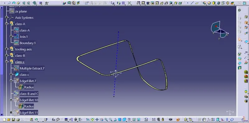
To create the class-C surface we extract the outer edge of the class-A surface. Using this boundary we use the sweep command to get the class-C surface. The class-C surface is the closing wall between the class-A and class-B surfaces. The angle between the class-A and Class-C surface is 90deg, so as with class B. Using the sweep command, we select the option 'from draft direction' and we provide an angle of 90deg. And the direction is towards the class-B surface. The image of the class-C surface is shown below.
After creating the class-C surface, we join both the class-B and class-C surfaces using the trim operation. The image of the output is shown below.
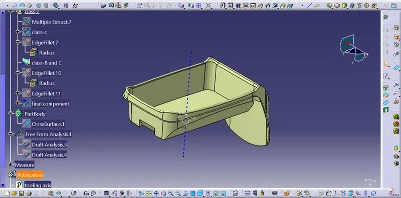
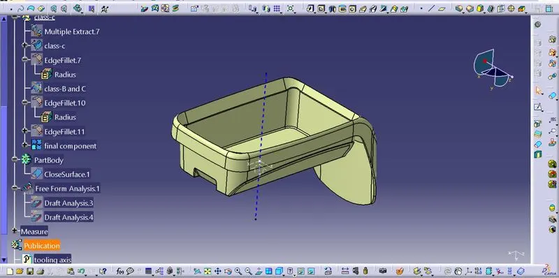
Once we have joined both the class-B and class-C surfaces, we unhide the class-A surface and use the join command to join all these three surfaces. Hence we have got the component of the required thickness of 2.5mm.
Draft analysis:
Draft analysis of class-A surface:
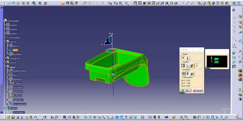
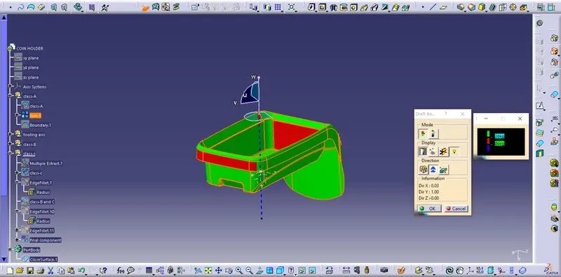
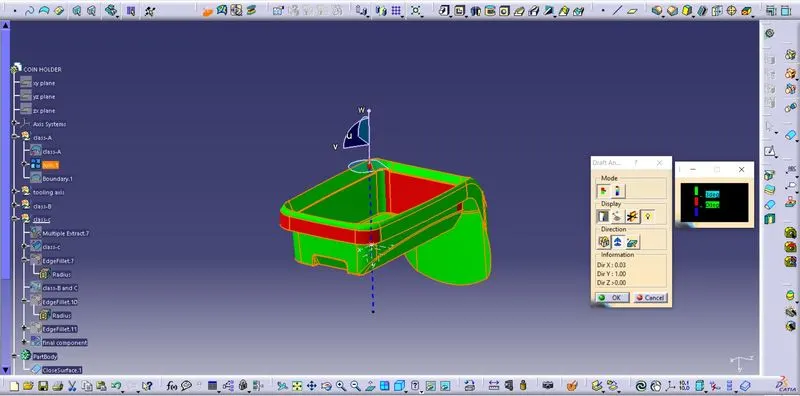
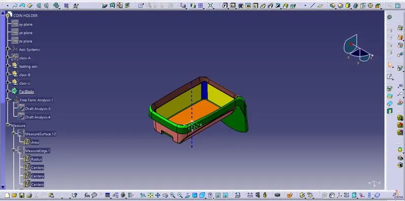
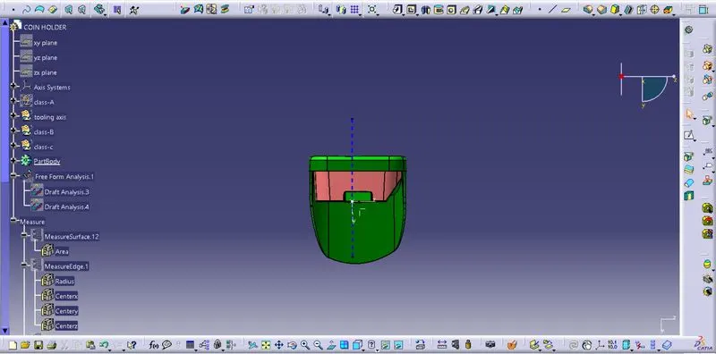
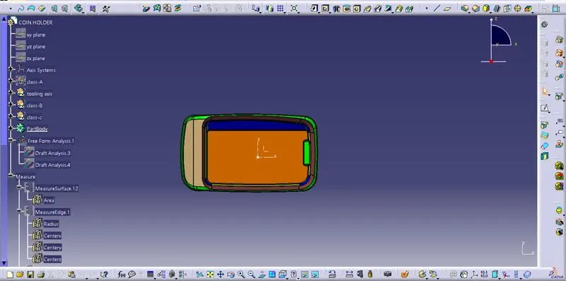
If the draft angle is taken as 1deg then the class-A surface is giving the output in green colour, whereas when we increase it to 2deg and 3deg draft angle, red colour patches are getting increased on the class-A surface. The images of the draft analysis are shown below.
1deg draft angle.
2deg draft angle.
3deg draft angle.
Draft analysis of thickened component:
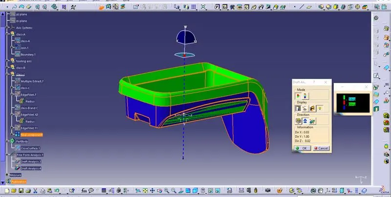
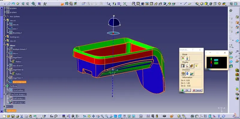
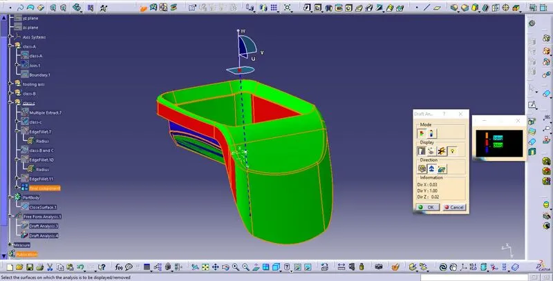
Same as the class-A surface the thickened component has given the green colour output in the draft direction with a draft angle of 1degree. whereas when we increased it to 2deg and 3deg draft angle the red colour patches started increasing on the surface.
The analysis images are provided below.
1deg draft angle.
2deg draft angle.
3deg draft angle.
Comparison of both class-A surface and final component:
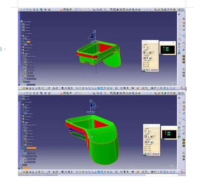
- Screenshots of the solid model with the proper colour code of the draft angle in various orientations (Isometric, Front, Side, and Top View).
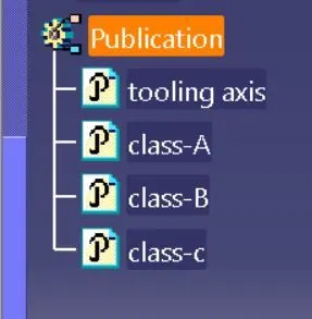
Publications:
Conclusion: From the given class-A surface we have developed the class-B and Class-C surfaces and joined them with the given class-A surface. But the draft analysis shows that changes have to be made to the clas-A surface so that the minimum three-degree draft angle requirement satisfies to eject the component easily.