Week 8 - Challenge 3 - Coin Holder Design
TOOLING AXIS:-
A tooling axis is the direction of a component where the component is easily ejected from core and cavity.
A tooling axis is a most important for removing material with very finished surface. Before start working in any component it is needed to create a tooling axis firstly.
Creation of tooling axis:-
Most probably the bisecting method is used for creation of tooling axis.
First of all need to analyse a component for best tooling axis
Now Extract a base surface and create a point (by using Point on surface)
Then insert a Axis System on a point.
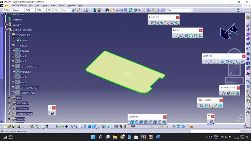
If our tooling axis is in Z direction then we need to find a tooling axis angle with X & Y Axis.
So Use a Bisecting method for it.
Firstly create a intersection from with class A and YZ plane
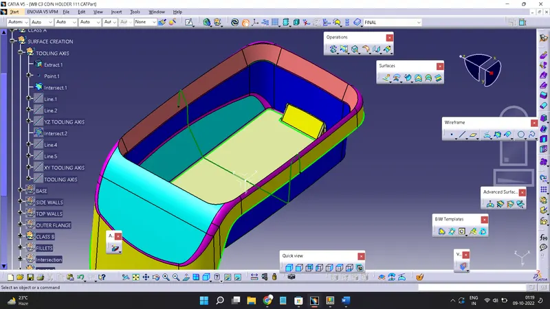
and create line in intersection then create bisecting line of these two line.
It will be YZ plane tooling Axis.
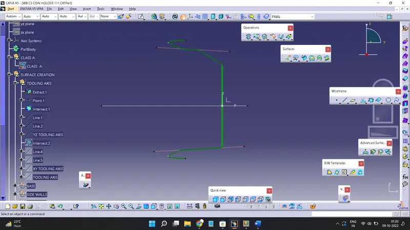
This same procedure needs to follow for XZ plane tooling axis
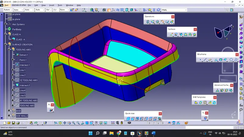
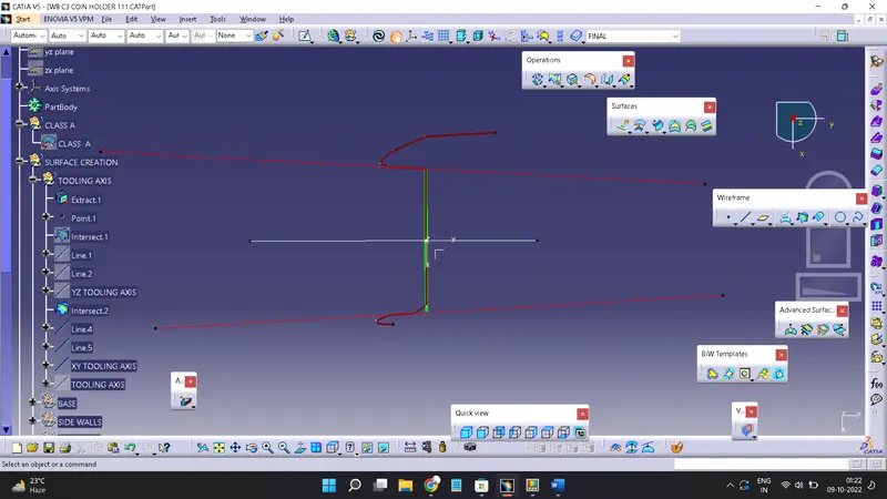
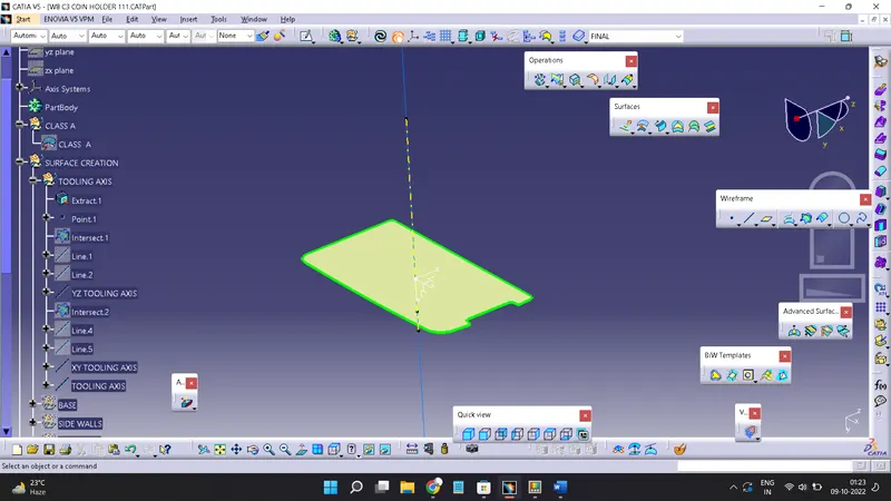
Now find a bisecting line of both YZ plane & XZ plane tooling axis.
It will be final Tooling axis of component.
SURFACE CREATION:-
Creation of CLASS B Surface:-
For surface creation divide component in different different part like Base, Side walls, Top walls, outer Flange etc.
Step 1. Extract the surface from CLASS A
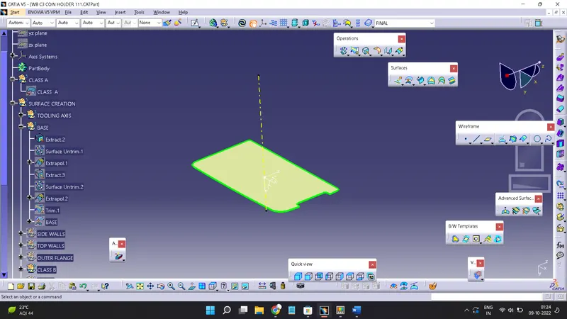
Step 2. Untrim all surfaces
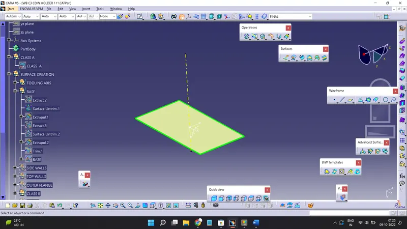
Step 3. Use Extrapolate for increase length/width of surface
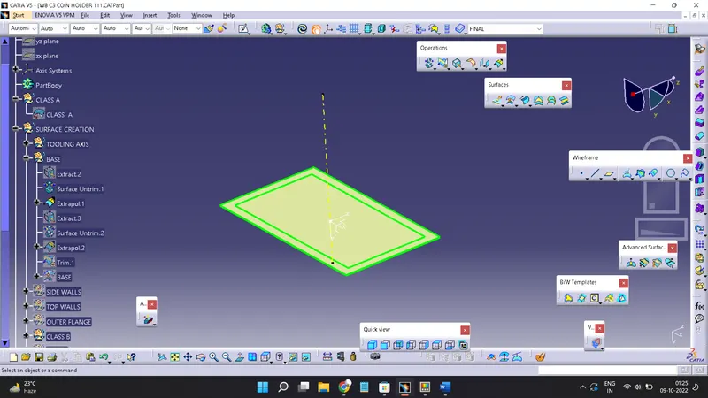
Choose same procedure for other surface which taken into Base.
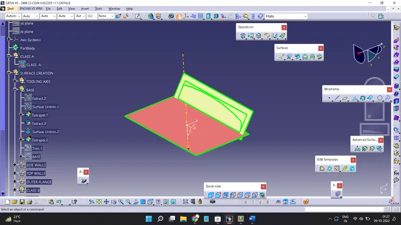
Step 4. Do untrim for removing unwanted surface
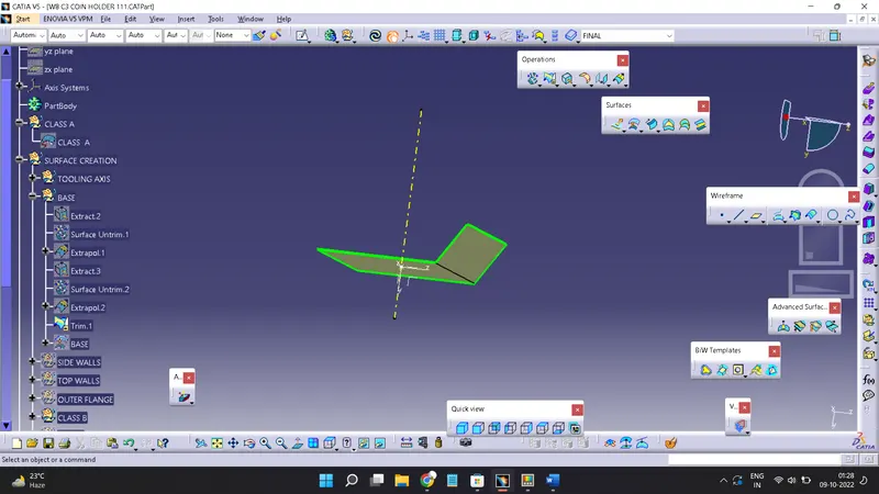
Step 5. Do offset for given thickness
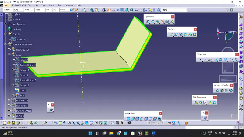
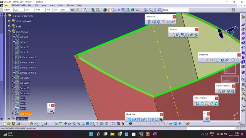
Extract all which is selected for Side Walls
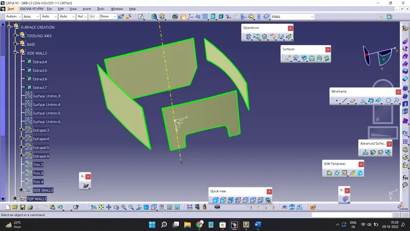
Do Untrim
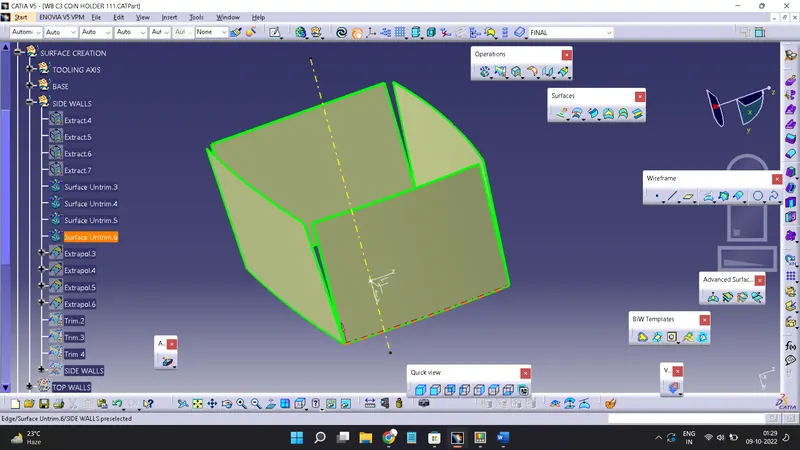
Do extrapolate
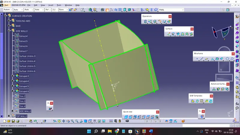
Then do trim for removing unwanted surfaces
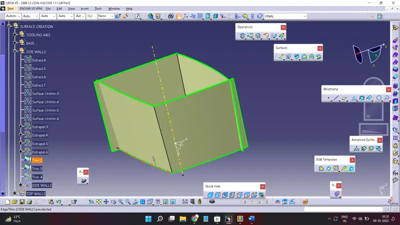
then offset surface
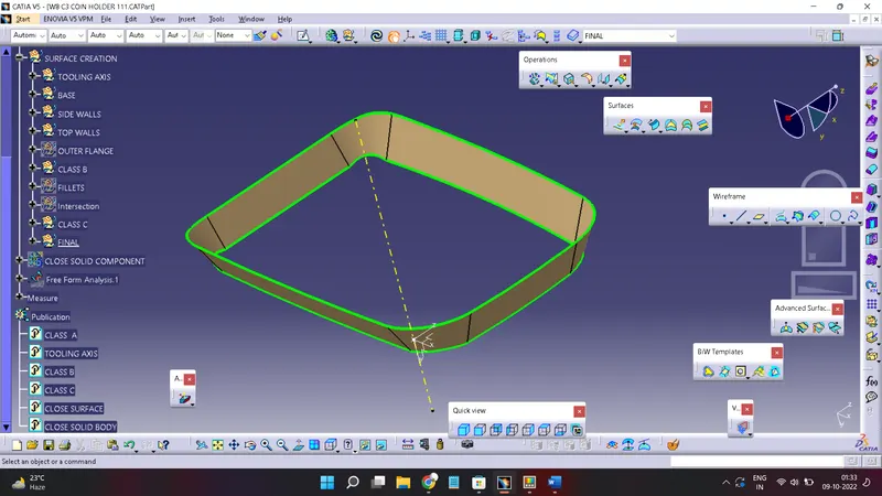
Do Same Procedure for Create Top walls
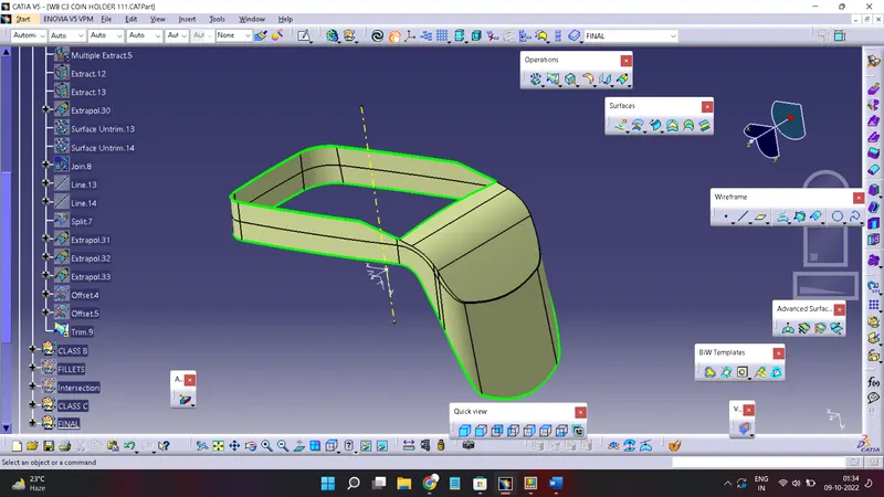
Do Same Procedure for Create Outer Flange
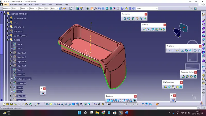
After creation of all the surface trim/join for create single surface
Creation of CLASS C:-
Here we need to create CLASS C perpendicular to tooling axis.
Step 1. create boundary of class A
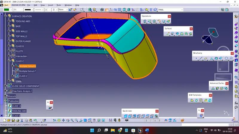
Step 2. Extract outer flange surface
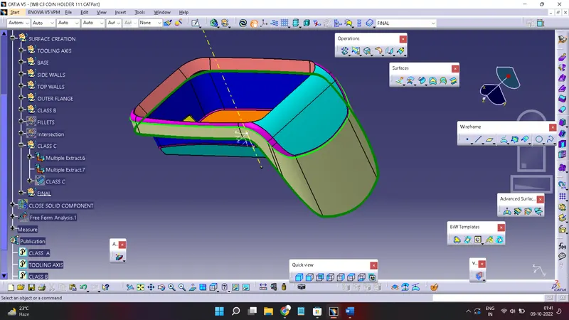
step 3. Use a sweep with line prototype, Subtype with reference surface
select bounday and extract with 90 degree.
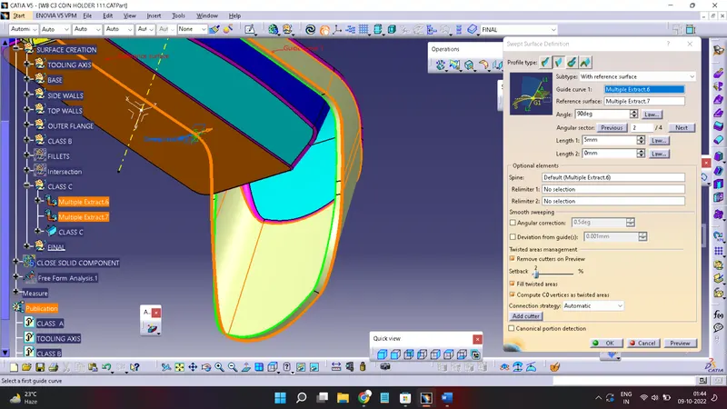
It is Class C Surface
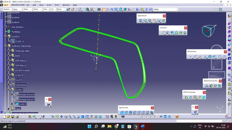
Now trim CLASS A & CLASS C
the unwanted surface will remove & usable surfface remains
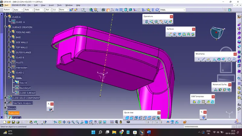
Then trim this surface with CLASS B & Get CLOSE SOLID COMPONENT.
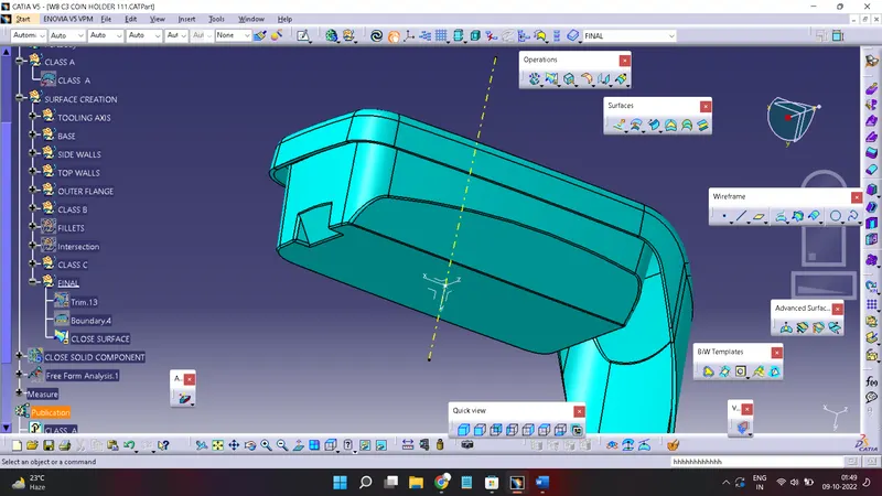
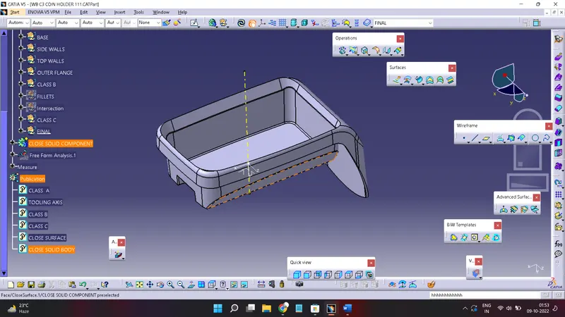
CREATION OF SOLID COMPONENT:-
goto Start>Mechenical Design> Part Design
Surface Based Features> Close Surface> Select close surface>OK
& hide surface
DRAFT ANALYSIS:-
A draft analysis is helps to detect a angle of a component. it will be easily removed. In catia a draft analysis is performed based on colour rain identify zones Using a draft and by using a draft analysis we can verify taper angle.
Examine angle change with a face as well as look at what time line and injection surface in parts
A draft analysis help to give a proper draft angle
Draft angle describe the amount of taper of mould which perpendicular to the party line
Minimum draft angle is required 3 degree.
DRAFT ANALYSIS of class A surface:-
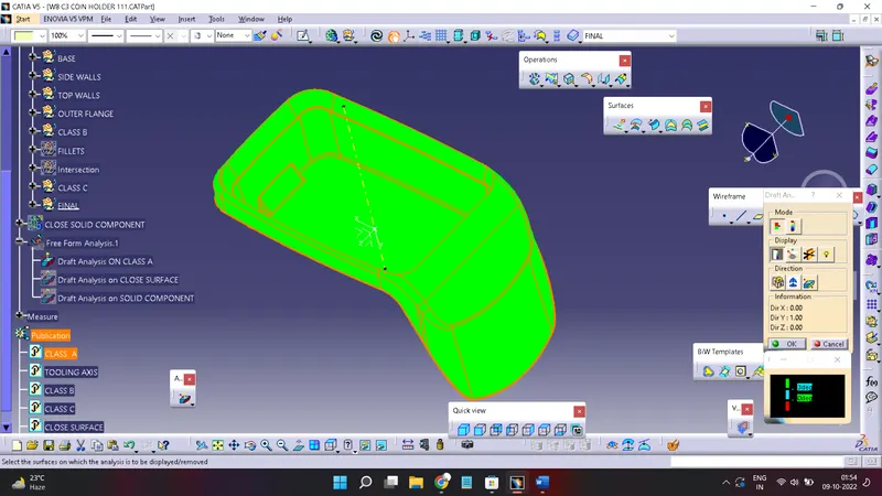
DRAFT ANALYSIS of close surface:-
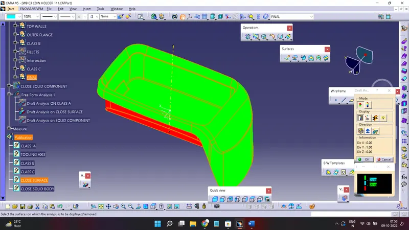
DRAFT ANALYSIS of close solid component:-
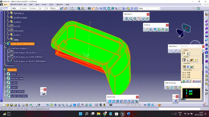
Creation Of Publication:-
Goto tools> Publication
Select Component which need to Publish then OK