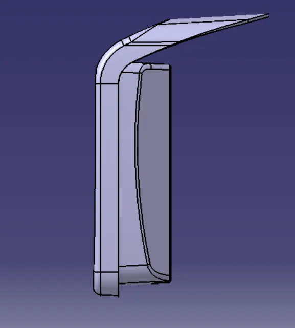
Week 8 - Challenge 3 - Coin Holder Design
COIN HOLDER DESIGN
AIM:- To create the coin holder plastic component through the given Class A surface. To begin with the tooling axis for the given Class-A surface should be created meeting the requirements of the draft angle and at the end perform the draft analysis on the model. Take the thickness of the component to be 2.5mm.
Objective :-
- To design coin holder as per automotive OEM Standard.
- Create B Class and C Class and tooling axis.
- Convert close lose the surface into the solid body and provide the thickness of 2.5mm.
- Performing draft analysis to verify the creation of the Tooling axis and C Class surface.
INTRODUCTION:-
CLASS-A SURFACE: a surface made by the designer which is given as an input to the plastic modeler to work on. It is aesthetic surface and the outer most surface.
CLASS-B SURFACE: a surface below a certain thickness from the class-A surface is class-B surface. This is the surface that contains engineering aspects of a model.
CLASS-C SURFACE: a surface that joins class-A and class-B surfaces is class-C surface.
Draft analysis: Draft analysis is performed on components where the ejection of materials happen after the material is made inside the tools.
METHODOLOGY:-
In this model we have focused on the following things:
Tooling axis
Draft analysis
Class-B surface
Class-C surface
Making a solid model from surface.
Following tools were used to reach the final step:
Extract
Un-trim
Trim
Extrapolate
Offset
Edge fillet
Boundary
Sweep
Join
Close (part design)
Design Methodology with images:-
- First visually check given Class A surface for to find out tooling axis which is cover all faces.
- Here the coin holder faces are stright so we can give tooling axis perpendiculer to base surface because the walls are stright if walls are have inclined we can choose other method like bisecting.
- Extract the base surface and create a point on center of extract base surface by using on surface point option.
Procedure for creating Tooling Axis
- Intersect the model with the plane perpendicular or to an axis system.
- Extend the lines which are perpendicular to the plane.
- Again intersect the model with another plane and extend the lines perpendicular to it.
- Create a bisecting line by bisecting option in Line definition.
- Rename it as Tooling Axis.
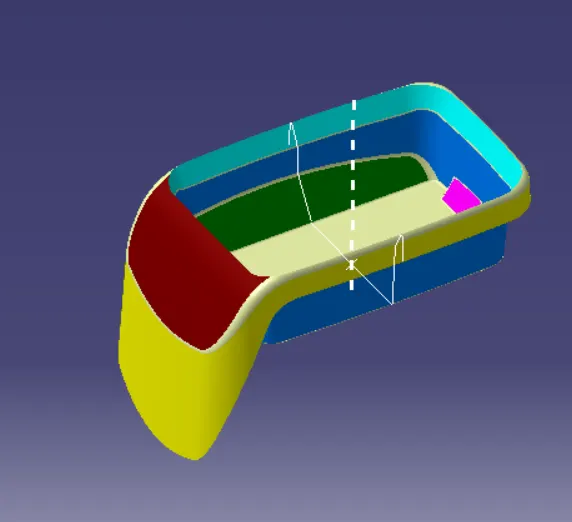
Procedure for creating B Class surafce:-
- Side Walls
- Base
- Top Wall
- Outer Flange (Final B SURFACE)
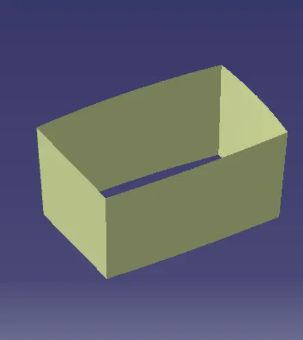
Side Walls:
- All the Operation of Side walls .
- Extract
- Surface untrim
- Extrapol
- Trim
- Offset
- Extract the side walls with no propagation in extract option.
- Untrim them.
- Extrapolate the walls with point continuity of distance 20mm.
- Trim the walls to get the required shape.
- Offset those trimmed walls with thickness value.
Top & Bottom Surfaces:-
- All the Operation of Top & Bottom Surface.
- Bottom Surface
- Extract
- Surface untrim
- Extrapol
- Trim
- Offset
- Trim
- Edge Fillet
ii. Top Wall
- Multiple Extract
- Extrapol
- Offset
- Trim
- Extract the surfaces separately and untrim them.
- Extrapolate the surfaces with required distances.
- Offset them with thickness value.
- Trim them for required shape.
- Measure the fillets, calculate it and create fillets.
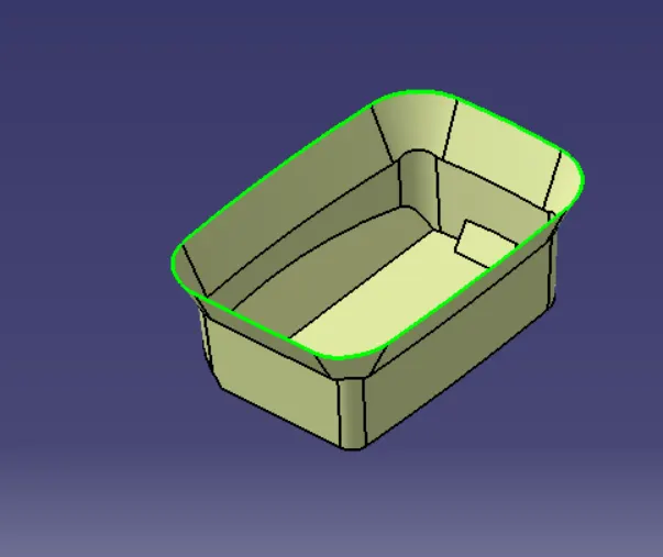
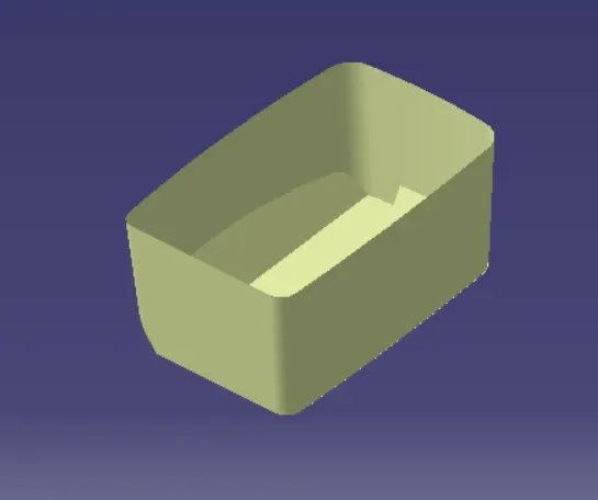
Outer Flange ( Finall Class B Surface):-
- All the operation of Outer flange
- Multiple Extract
- Extrapol
- Offset
- Boundary
- Trim
- Join
- Multiple Output
- Surface Untrim
- Edge fillet
- Final B Surface
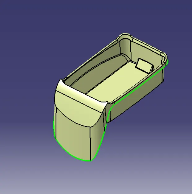
Procedure for creating Class C Surface:-
- All the operation of Class C Surface.
- Boundary
- Join
- Sweep
- Class C to Class A Join
- Get the boundary lines of Class A surface separately.
- Smooth the curves with a smooth option as boundary lines have a lot of vertices.
- Sweep the curves with tooling axis as direction in Sweep option.
- As both lines do not intersect, extrapolate them with a certain distance.
- Trim the surfaces.
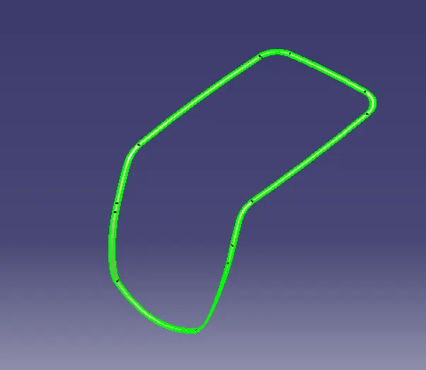
CLASS C SURFACE TO CLASS A SURFACE JOIN.
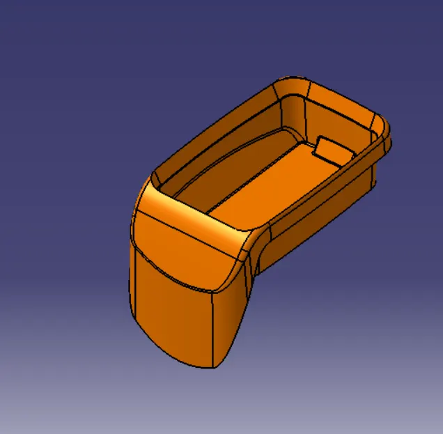
FINAL TRIM:-
- Extrapol
- Edge Fillet
- Trim (CLASS B SURFACE TO CLASS C SURFACE)
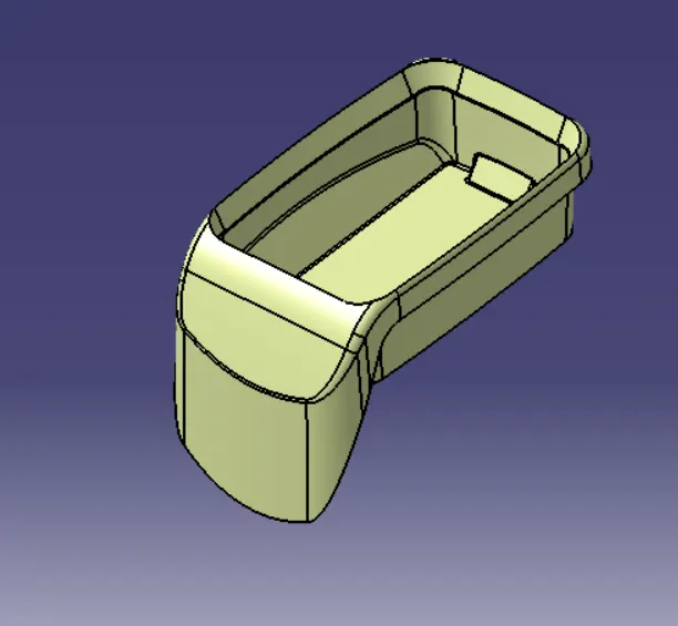
Procedure for creating Closed Body:-
- Join the Class A and Class C surfaces.
- Trim those joined surfaces with Class B surfaces.
- Go to Part Design and insert a Body.
- Create a closed surface.
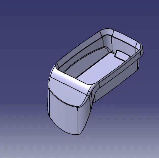
Draft Analysis :-
The Draft angle is the amount of taper for molded or cast parts perpendicular to the parting line. It can be measured in degrees. A functional part for injection molding has to have drafts facing both cavity and core sides to reduce the risk of damage to the parts and ensure ejection. And also important is to overcome the vaccume forces by letting air in between the metal and the plastic for the part to release properly. Adding maintaining a decent cosmetic finish.
Draft should be a part of design for manufacturing and plastic product Designer should be aware of its need at the outset of the design process. This allows considerations for design requirement to be taken into account.
Nominal values for Draft angle :
- 3 Degrees is the nominal Draft angle.
- 7 Degrees for textured surface.
- At the minimum of 0.5 Degrees can be manufactured by special tools. But it will increase the manufacturing cost.
Procedure for creating Draft Analysis:-
- Go to the Insert menu and select the Analysis option.
- Select Feature Draft Analysis.
- Select the Material option and select the surface.
- Drag the compass and place on tooling axis.
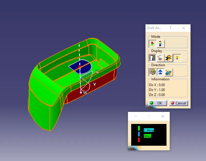
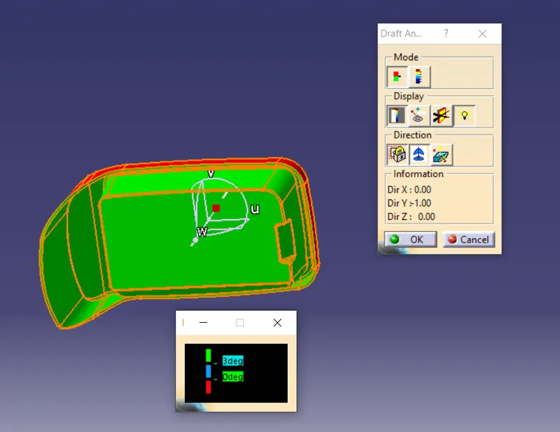
- Make sure that the top surface is in green colour as draft angle should not exceed 3deg.
- Click on Okay after confirm the model.
Top side Draft analysis.
Bottom Side Draft analysis.
Isometric View.
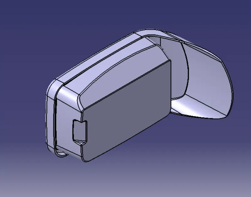
Front View.
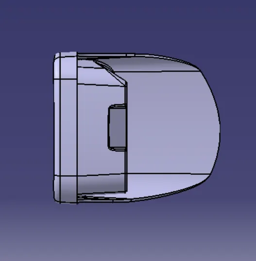
Left side view.
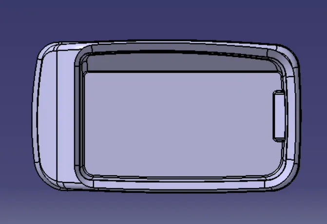
Top View.