Photo Realistic Rendering
American Chopper Bike
Objective :- To design part of the american chopper bike.
Assembly of the part to from whole bike and photo Realistic rendering of the assembly.
Introduction :- in this project we are designing the American chopper with the help of blueprint given,with the help blue print we can get the basic dimensions of the chopper and we can desig all parts of the american chopper.after this we do assembly of all parts now,we have our American chopper assembled,now we can add decals parts,next we adjust the camera and light according to the view point.the last step is doing rendering with the help of solidwork visualization software.
Design methodology :- FLOW CHART OF AMERICAN CHOPPER
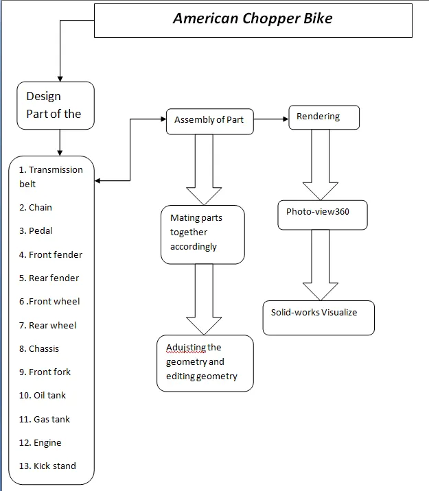
Description/Design Methodology with the Image of part file:-
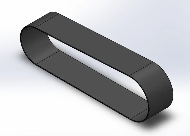
1. Transmission belt
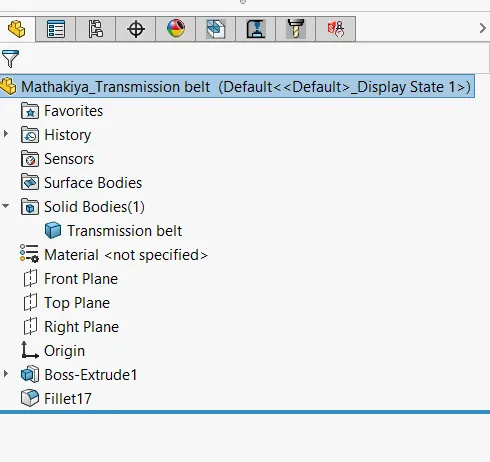
Features use to create the transmission belt.
- Sketch
- Offset
- Extrude
- Fillet
- Appearances
Isometric view of transmission belt with Feature tree
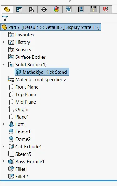
2. Kick Stand
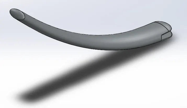
Features used to create the kick stand
- 2D Sketch
- ellipse
- spline
- pierce
- loft
- cut extrude
- boss extrudes
- split
Isometric view of kick stand with the feature tree.
3.Front fender
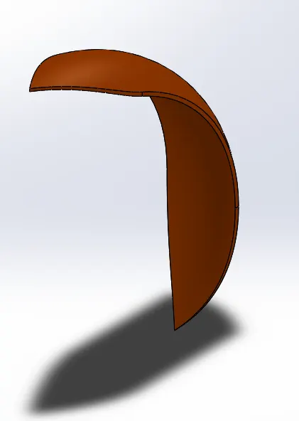
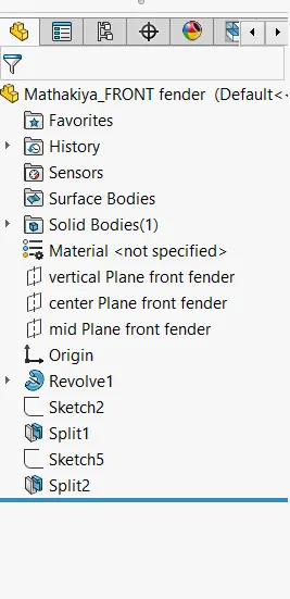
Feature used to create thr front fendr.
- 2D Sketch
- 3Point arc
- offset
- extend
- trim
- revolve
- spline
- fillet
Isometric view of front fender with feature tree
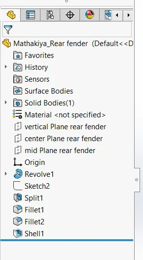
4.Rear Fender
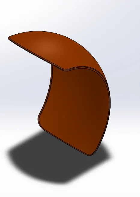
Feature used to create rear fender.
- 2D Sketch
- 3Point arc
- offset
- extend
- trim
- revolve
- spline
- fillet
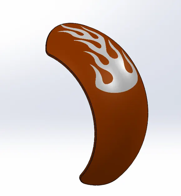
Isometric view of Rear fender with feature tree. Decals of rear fender.
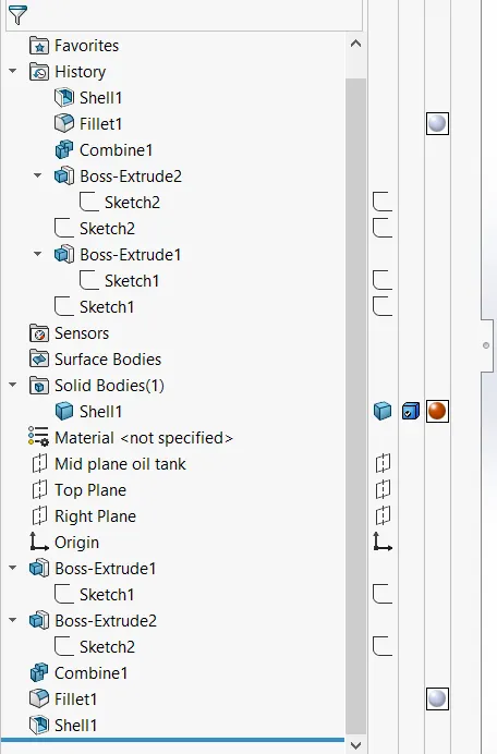
5.Oil tank
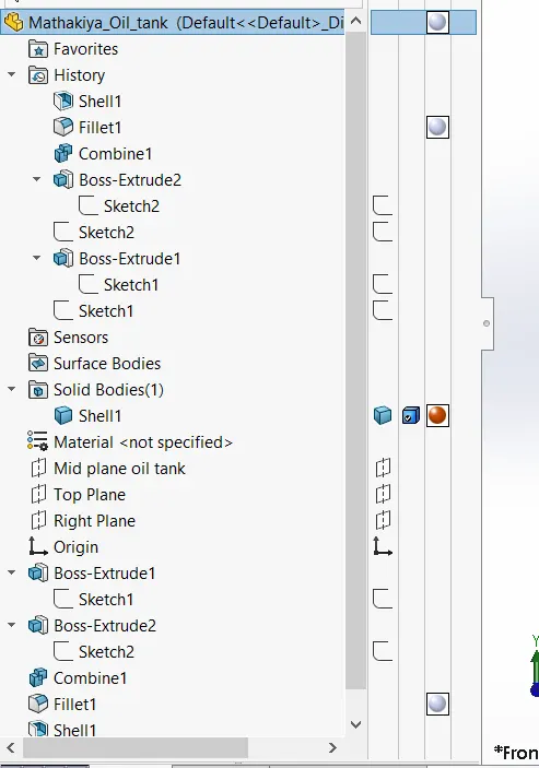
Feature used to create the Oil tank with feature tree.
- line
- 3point arc
- boss extrude
- combine
- fillet
- shell
Isometric view of oil tank with feature tree
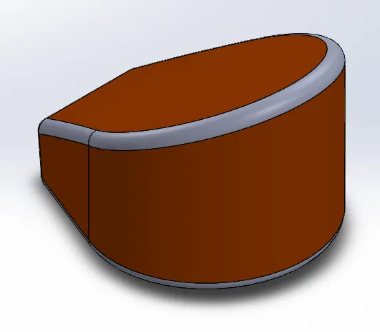
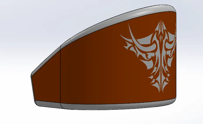 oil tank with Decal
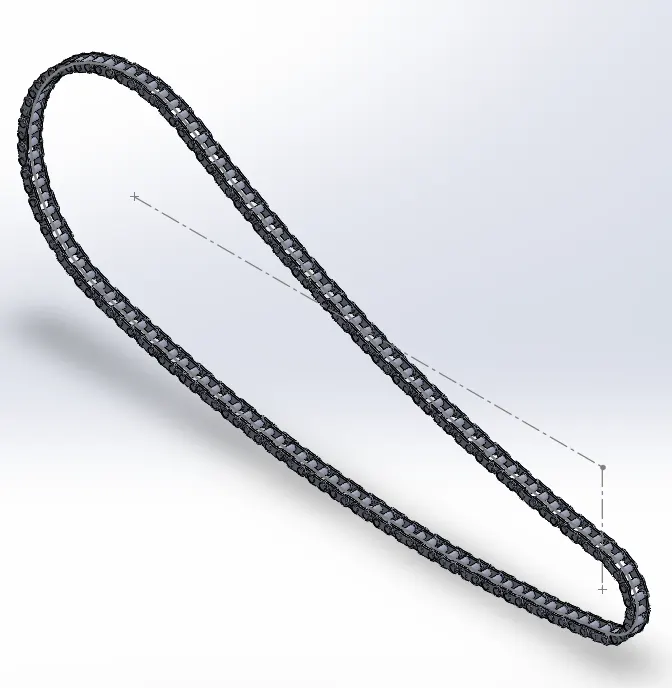
6.Chain
Feature used to create the chain
- 2D Sketch
- circles
- 3point arc
- Slot
- Block
- Fillet
- Curve pattern
- Mirror
Isometric view of the chain
7.Pedal
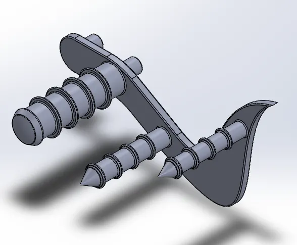
Feature used to create pedal
- 2D Sketch
- line
- circles
- fillets
- revolve
- dome
- chamfer
- linear pattern
Isometric view of the pedal
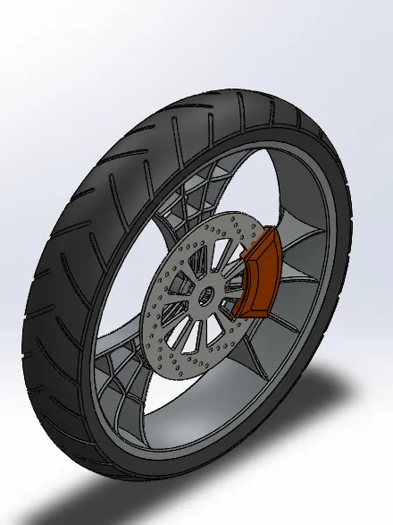
8.Front wheel
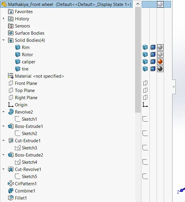
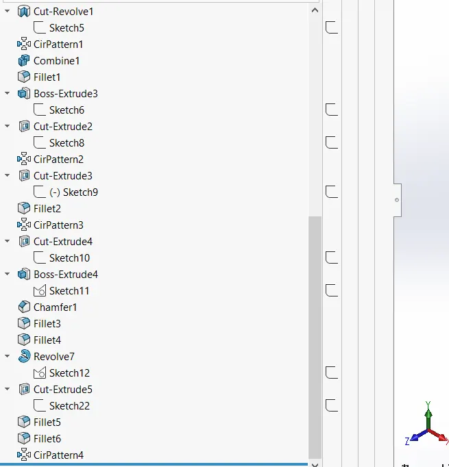
Feature used to create front wheel
- 2D Sketch
- Straight lines
- 3Point Arc
- Sketch
- fillet
- revolve
- spline
- extend
- trim
- cut extrude
- offset
- cut revolve
- circular pattern
- chamfer
- fillet
- corner center point rectangle
isometric view of front wheel with feature tree
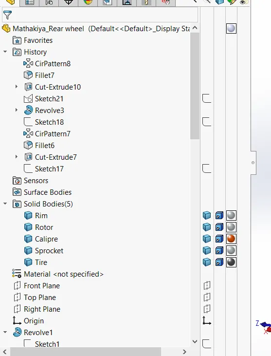
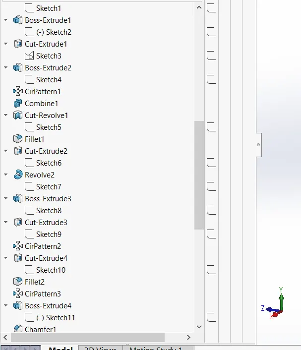
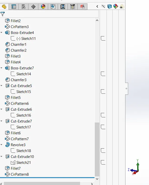
9. Rear wheel
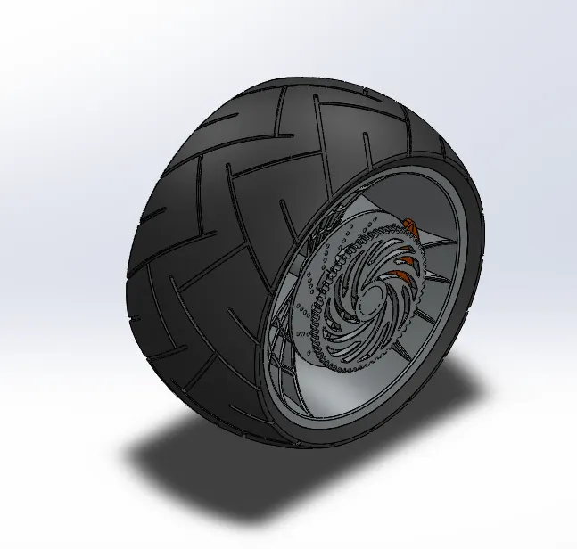
Feature used to create the rear wheel
- 2D Sketch
- Straight lines
- 3Point Arc
- Sketch
- fillet
- revolve
- spline
- extend
- trim
- cut extrude
- offset
- cut revolve
- circular pattern
- chamfer
- fillet
- corner center point rectangle
Isometric view of rear wheel with feature tree
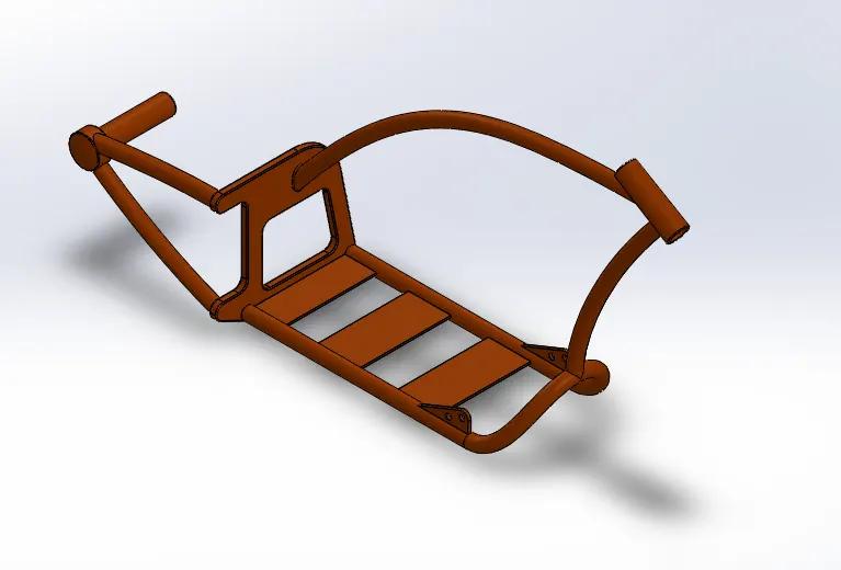
10. Front Fork
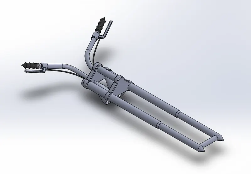
Feature used to create the front fork
- 2D Sketch
- Straight line
- Revolve
- Circle
- Fillets
- linear pattern
- spline
- cut extrude
- dome
- move body
- curve
- sweep
- plane
- mirror
- combine
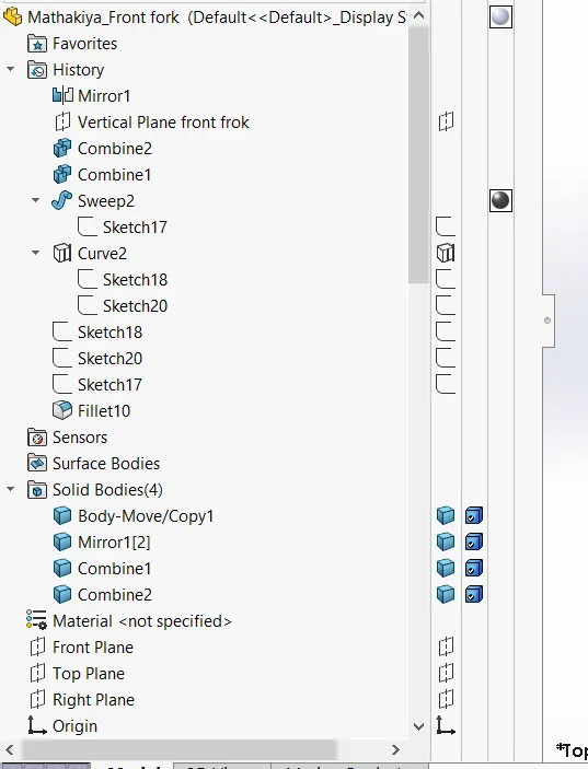
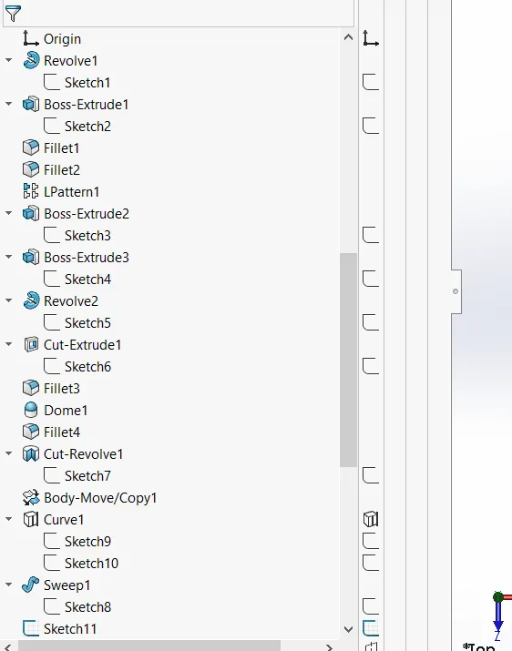
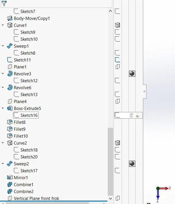
Isometric view of Front fork with feature tree
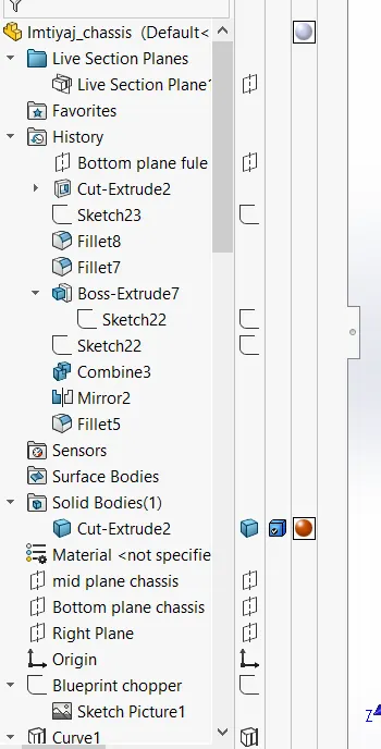
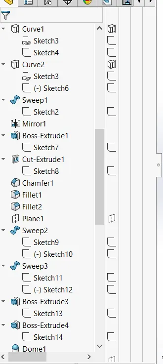
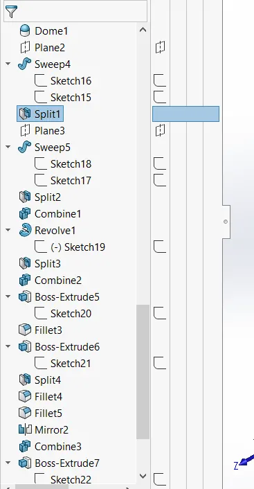
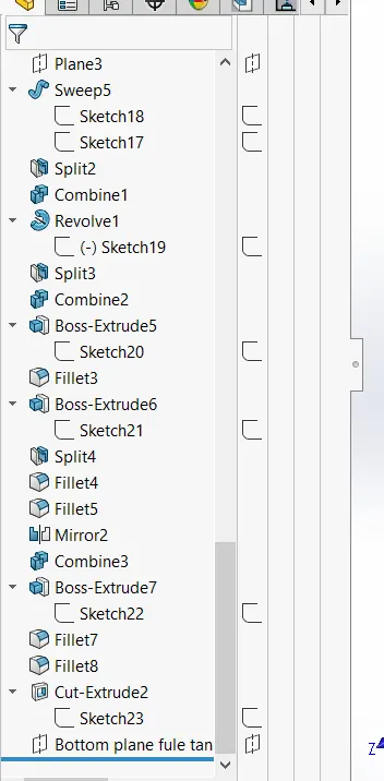
11.Chassis
Feature used to create the chassis
- Sketch picture
- splines
- curves
- mirror
- boss extrudes
- cut extrude
- chamfer
- dome
- split
- revolve
- combine
Isometric view of Chassis with feature tree
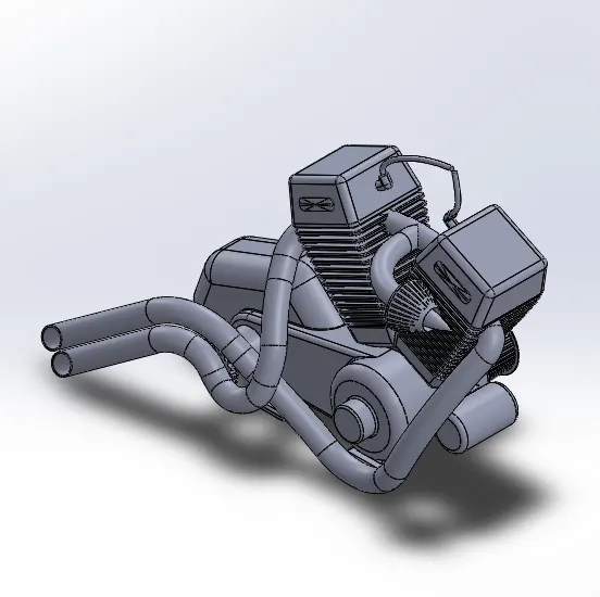
12. Engine
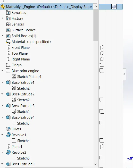
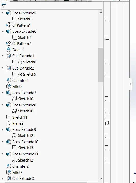
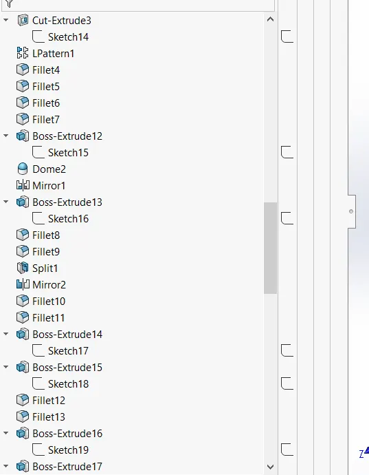
Feature used to create the engine
- 2D Sketch
- Sketch picture
- straight line
- circles
- boss extrude
- fillets
- revolve
- plane
- dome
- circuler pattern
- chamfer
- linear pattern
- mirror
- cut extrude
- combine
- mirror
- curve
- composite curve
- spilt
isometric view of the Engine with feature tree
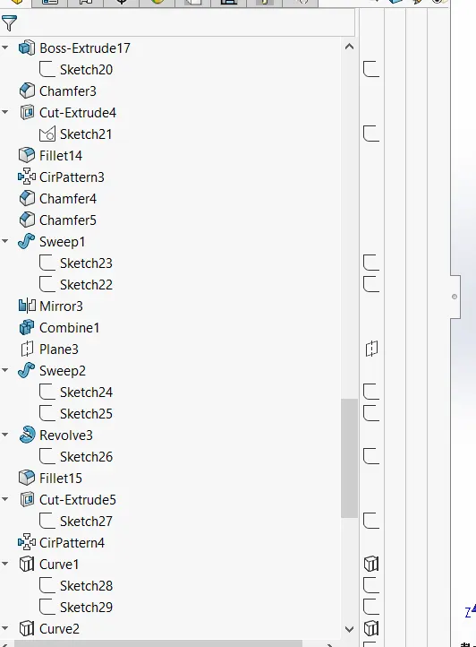
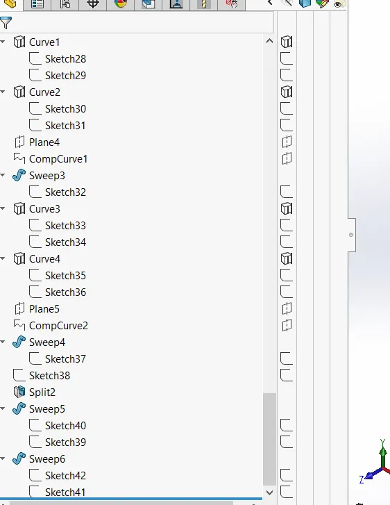
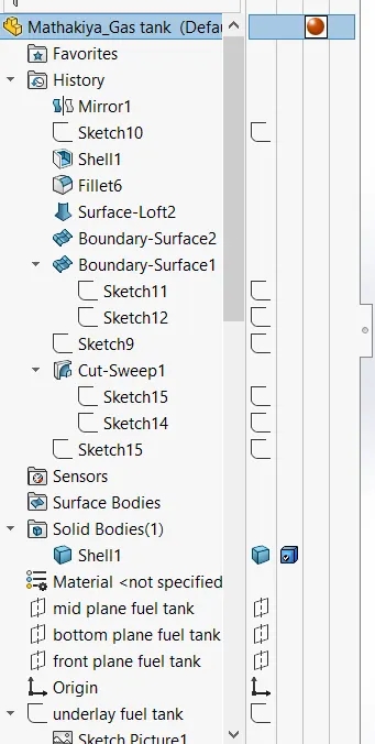
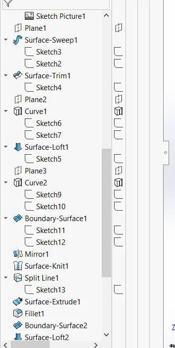
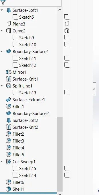
13. Gas tank
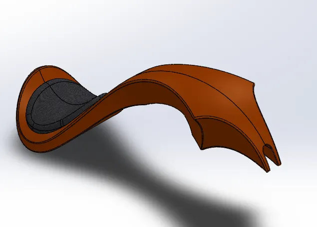
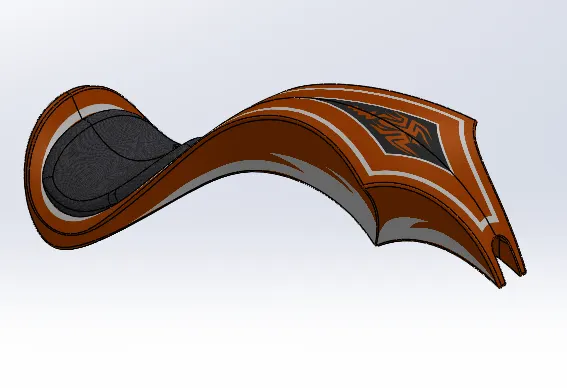
Feature used to create gas tank with feature tree
- 2D Sketch
- spline
- Surface sweep
- Surface trim
- Surface boundary
- Surface loft
- curve
- mirror
- surface kint
- surface extrudes
- fillet
- cut extrude
- shell
Isometric view of the gas tank with feature tree
Assembly of model / Render :-
Front view of Assembly with rendering. Left side view of assembly with rendering.
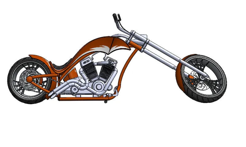
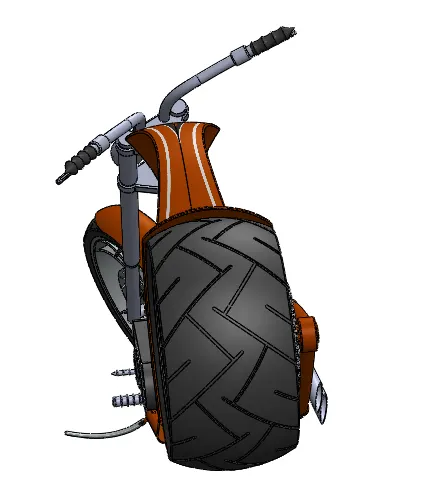
Right side of Assembly with rendering Top side of assembly with rendering.
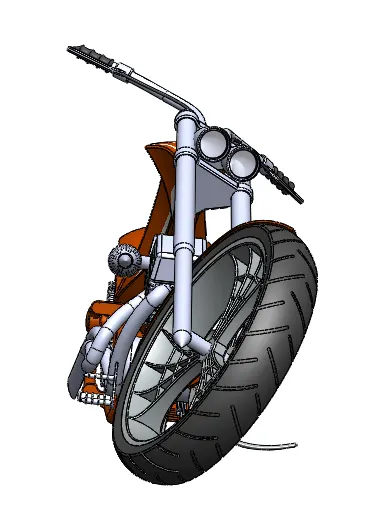
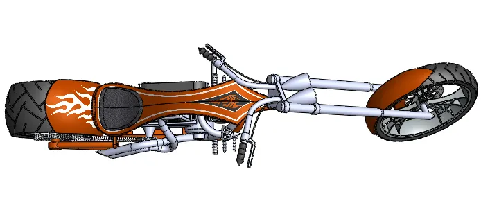
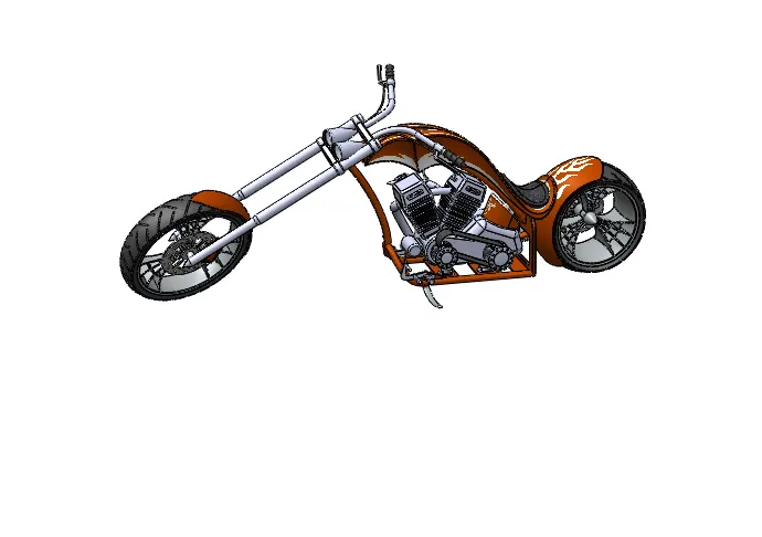
Camera view of Assembly with rendering
Conclusion :- We learned basic to advanced tool to do modeling of American chopper in solidwork. learned how to start a design from sketching to modeling as all industries do. learned how to adjust lights,camera,backplate, and environment to get the best rendering effect by usign Solidworks visualization.