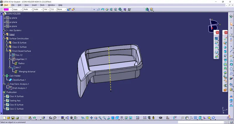
Week 8 - Challenge 3 - Coin Holder Design
1st Step - Check the connectivity of the Class A Surface
(A surface made by the designer which is given as an input to the plastic modeler to work on. It is aesthetic surface
and the outer most surface.)
- Ensure that there is no gap between the component, using join command.
- We can visually check it or by clicking boundary command.
- It has 3 boundaries one outer and two inner circle boundaries.
- Therefore first check completed.
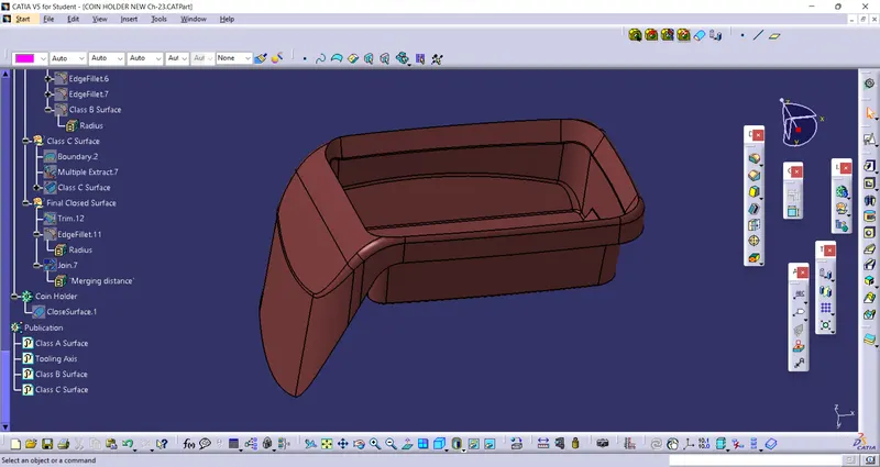
2nd Step - Find the tooling axis of the component.
(The Tooling Direction is basically the direction that the mold pulls a part. The mold is built in two separate pieces, basically. You have a Cavity side and you have the Core side. The Core pulls apart from the Cavity and that's the Dye line or the Tooling Direction.)
- Check visaully which is the best possible tooling axis.
- Check all three axis.
- Y is the best possible tooling axis.
- EXPLANATION ON BISECTING METHOD:
- Bisecting method is basically use to find the proper tooling axis using the dummy tooling axis. In Bisecting method, bisecting line is used which either bisect the two line or it will show error which means the two lines are parallel to each other. In order to know whether the particular surface is toolable or not we intersect the surface with the respective plane and get a sketch which consist of two lines and with the help of bisecting line option we bisect the line which creates a line at the mid point of the two lines. Like wise we create tooling clearing axis for x and y which will be used to create the main tooling axis using the bisecting line option in in the line comand.
- EXPLANATION ON BISECTING METHOD:
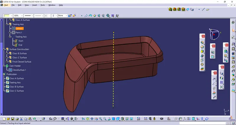
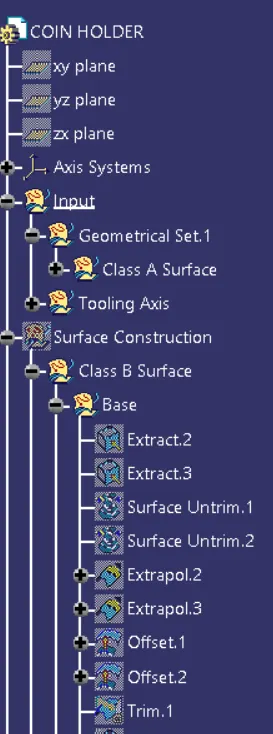
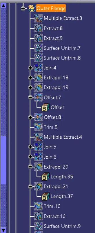
3rd Step - Now creating Class B Surface
(A surface below a certain thickness from the class-A surface is class-B surface. This is the surface that contains
engineering aspects of a model.)
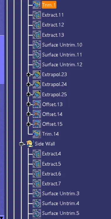
- Intially extracting the right side rib using Extract feature from Class A surface.
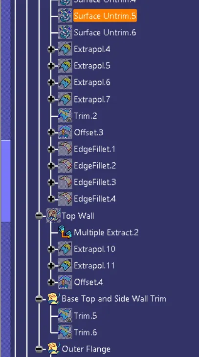
- Then perform Untrim followed by Extrapolate inorder to increase the length
- Now trim the surfaces to required surfaces
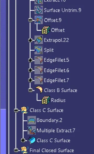
- Then Offset the surface inorder to get the required thickness
- Similary create the left side rib
- Now Similarly get the slanted as well as the flat surface and offset it to desired value
- And now trim inorder to get the required surface
- Now fillet the surface to required amount
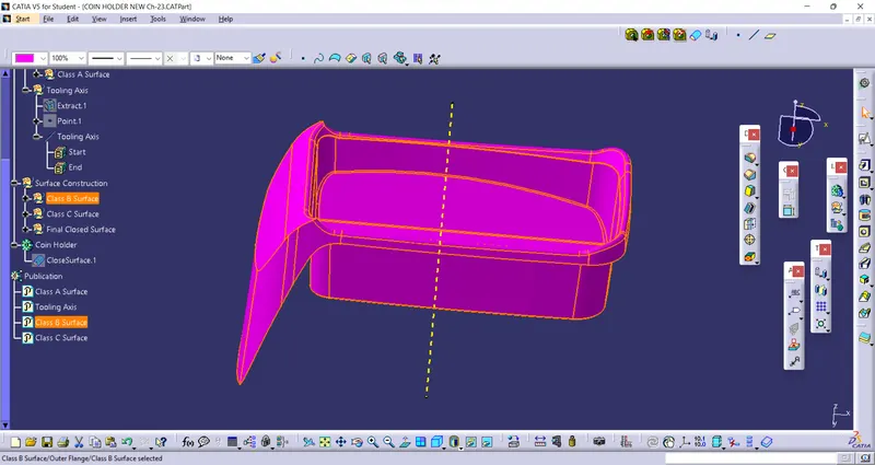
4th Step - Creating Class C Surface
(A surface that joins class-A and class-B surfaces is class-C surface.)
- Create Boundry around Class A Surfaces
- We will Get 3 different Boundaries 2 for holes and 1 for outer boundary
- Use Sweep feature with subtype - "With Draft Direction"
- Provide 3 degree as angle
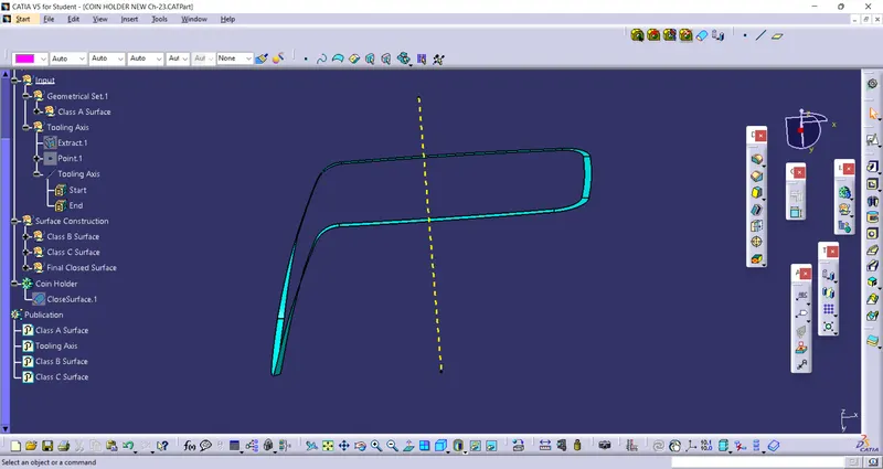
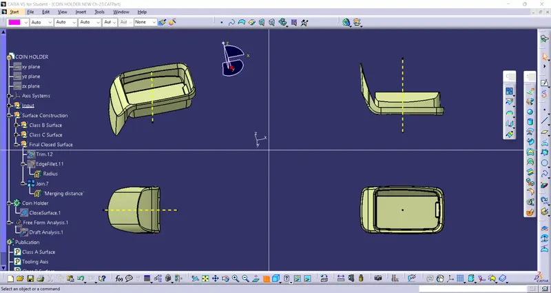
5th Step Draft Analysis
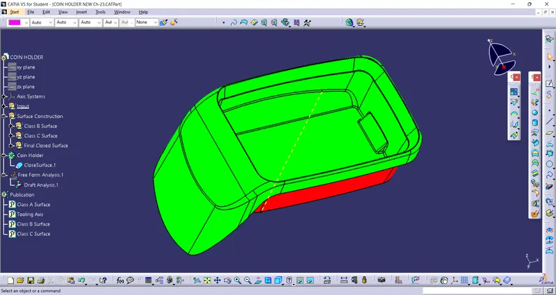
The Draft Analysis command enables you to detect if the part you drafted will be easily removed. This type of analysis is performed based on color ranges identifying zones on the analyzed element where the deviation from the draft direction at any point, corresponds to specified values.
- Before going to Draft Analysis go to customized view parameter >under mesh >check material and then click ok.
- Now for draft analyses go to insert » analysis » feature draft analysis.
- Use the compasss to define the draft direction.
- In the colour scale change the draft angle to 3 degree.
- The component changes to green in indication of passing draft angle.
- Use running point to check the angle on the component.
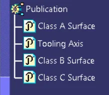
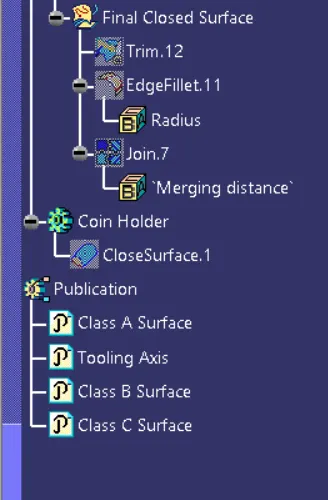
PUBLICATION
- Publication is done to the component to make it visible and navigate easily.
- To publish the component go to tools > publications and then select the tooling axis and the class A,B & C surface.
- A separate tree structure is formed under the main part.