Week 8 - Challenge 3 - Coin Holder Design
AIM: To Create the Coin Holder Plastic component through the given Class-A surface. To begin with, the tooling axis for the given Class-A Surface should be created meeting the requirements of the draft angle and at the end perform the Draft analysis on the model.
Take the Thickness of the component to be 2.5 mm
PROCEDURE FOR DESIGNING THE COIN HOLDER COMPONENT :
Class A surface: Class A surface is a Styling surface or aesthetic surface get it from the styling team. we will design the plastic component by using the Class A surface as input.
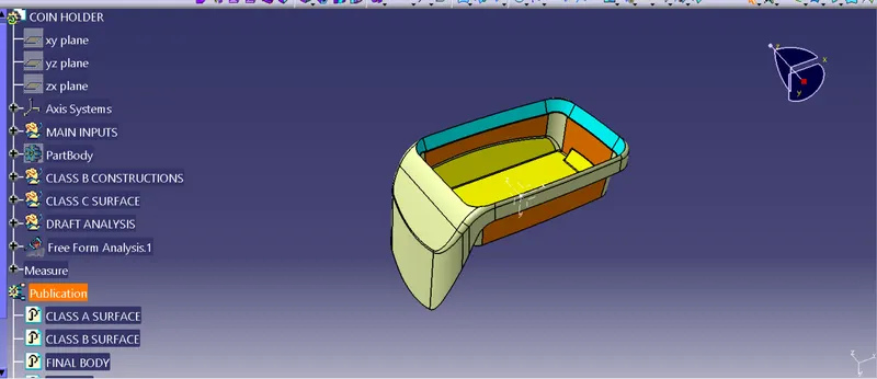
- Check all the views of the given class A surface that can help us to understand and get more understanding of the component.
- Connectivity of the class A surface that there is no gap between the component, by using joining command or boundary command we can check.
CREATING THE CLASS B SURFACE
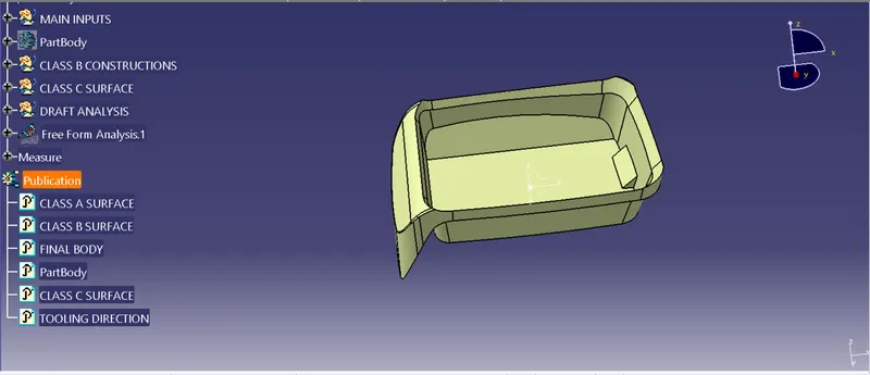
- Class B surface is to be creating the engineering features and offsetting the surface of class A. Firstly we will extract surfaces by using the extract command and from the class A surface.
- Then extend the sides by using the Extrapolate which will help to increase the length of the trim and, Trim the excess surface which is not required by using the trim command and is the same as the other side.
- After creating the side ribs we can again extract the middle base surface and extend the surface and offset the surface
after the main surface is also the same process as the middle base surface. - And given the fillet to the sharp corners where the dimension is taken from the class A surface and given to the class b surface.
CREATING THE CLASS C SURFACE
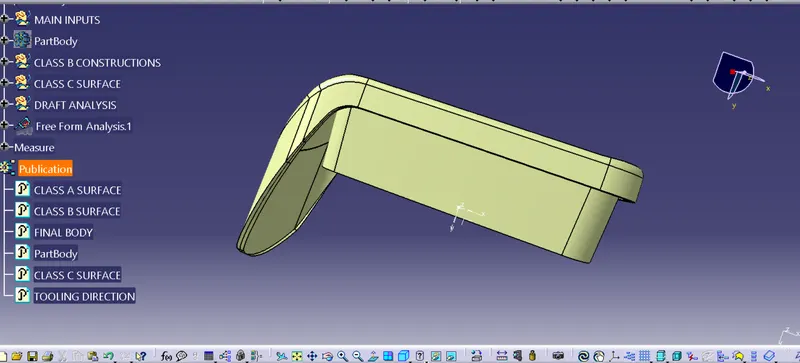
- Class C surface is connected the Class A and Class B, For the class C surface, we need to create the entire boundary of the component by using the boundary command.
- And also creating the best way for the tooling direction to manufacturing easily in an effective way.
- By using the sweep command we can combine them and trim the surfaces so we can get the completed closed surface body and draft angle given as 3 degrees.
- Before trimming the most importing things to join them all.
- After the body has to be closed by using the closed surface in part modeling.
TOOLING DIRECTION & BISECTING
- The tooling direction would be at the z-axis because at that direction it is very easy to manufacture and all the and all faces and the entire surface are to be covered in that direction without adding any other equipment
Bisecting, the articular surface is a tool or not we intersect the surface with the respective plane and get a sketch which consists of two lines, and with the help of bisecting line option, we bisect the line which creates a line at the midpoint of the two lines. Likewise, we create a tooling clearing axis for x and y which will be used to create the main tooling axis using the bisecting line option in the line command.
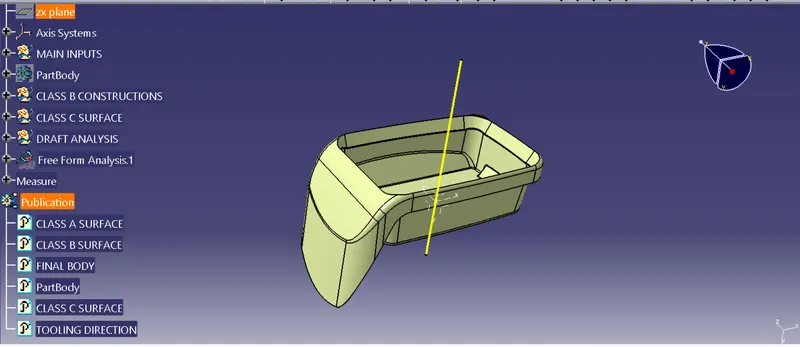
VARIOUS ORIENTATIONS OF THE FINAL COMPONENT
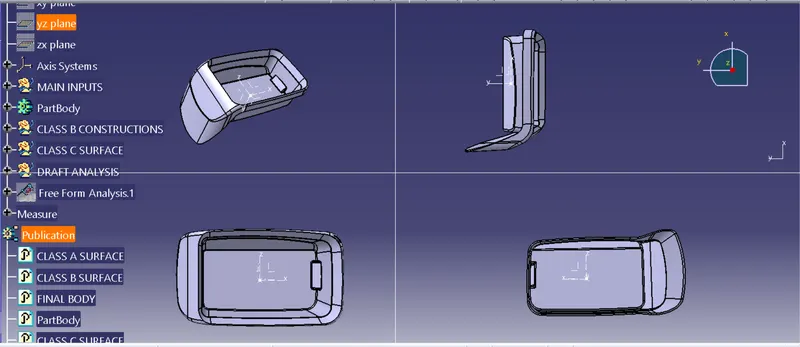
DRAFT ANALYSIS
- Draft Analysis for the Class A surface:
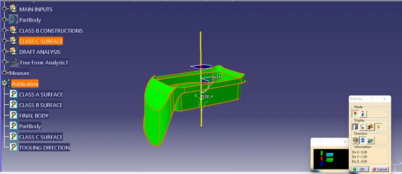
- Draft Analysis for the Final Plastic body:
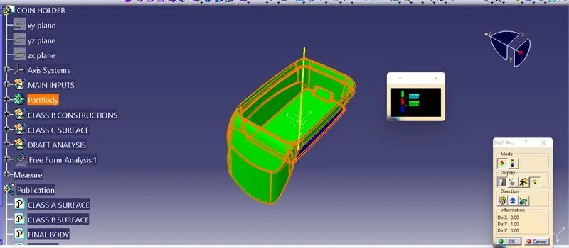
CONCLUSION: Finally the Coin holder Plastic component has been created through the given Class-A surface, with the tooling axis for the given Class-A Surface created meeting the requirements of the draft angle and at the end performing the Draft analysis on the model.