Week -2
AIM: To Make a Simulink model of Doorbell using a solenoid block with the following details
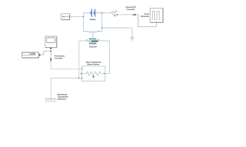
Given diagram:
Solenoid: It is a type of electromagnet formed by a helical coil of wire whose length is substantially greater than its diameter, which generates a controlled magnetic field. The coil can produce a uniform magnetic field in a volume of space when an electric current is passed through it.
Procedure:
- There are many blocks used in the simulation
- the pulse generator is used to generate square wave pulse at regular intervals
- switch is used to control an external physical signal
- battery, it gives voltage to the system
- Simulink -ps converter converts the Simulink input signal to a physical signal.
- solenoid block shows the position of the plunger with respect to the EMF induced
- ideal translational motion sensor is an ideal mechanical translational motion sensor, that is a device that converts an across variable measured between two mechanical translational nodes into a control signal proportional to velocity and position
- scope is to view the characteristics of a property with respect to the time
Simulink Model:
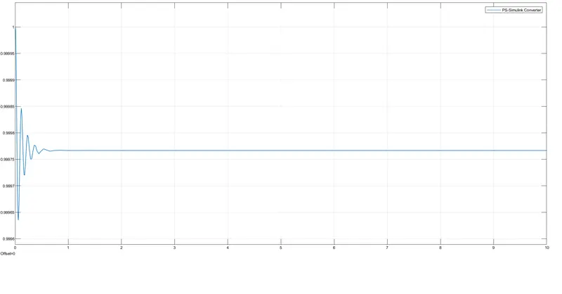
Plot for the Simulink
2. Use a thermistor to sense the temperature of a heater & turn on or turn off the fan
Conditions:
Temperature source: 20 °C from 0 to 10 seconds, 27 °C from 10 to 30 seconds, 23 °C from 30 to 50 seconds
Fan conditions: ON if the temperature is above 25 °C, OFF otherwise
Blocks used in the model:
- Repeating sequence stair
- battery
- switch
- Display
- Scope
- Controlled temperature source
- Thermistor
- Resistor
- Voltage sensor
- PS- Simulink converter
- Simulink - PS converter
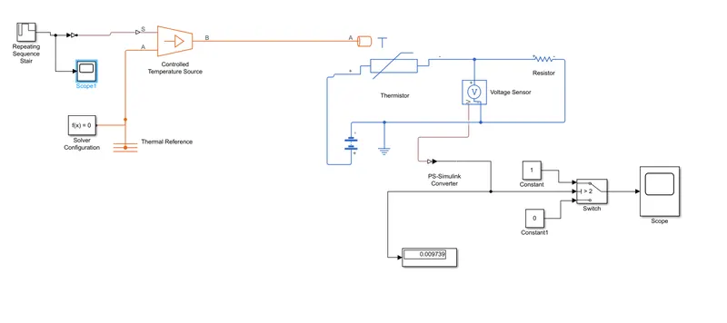
Simulink model:
Model Explanation:
A repeating sequence stair is given as input to the thermistor through a controlled temperature source. the definition of a Repeating sequence stair block is given below.
The conditions of the temperature source are defined inside the above window.
The sample time was taken as 10s and the whole simulation time was taken as the 50s.
A battery and a resistor are connected in the thermistor circuit.
A voltage sensor was given across this resistor to measure the voltage change during different temperature inputs.
The resistance of this resistor can be set to any value.
-------------------------------------------------------------------------