Week 8 - Challenge 3 - Coin Holder Design
COIN HOLDER DESIGN:
Tooling axis: -
Coin holder is a component with a complex geometry but the symmetrical shape of it makes it easier to predict the tooling direction. The bottom plane face of the coin holder is extracted and a point is created in the middle of the extract. Using the point as a reference, a line normal to the extract is created which is the tooling axis. This method is preferred for this part instead of bisecting method as it saves time and steps required to create the tooling axis.
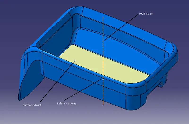
For the bisecting method, the point in the middle of the extract can be taken as reference and used to create an axis system. The planes which are perpendicular to the inner faces and the plane of symmetry can be used to make positioned sketch. Using the intersection of the selected plane and the Class A two construction lines can be created which can then be bisected to obtain the tooling axis. The axis obtained will be of the same direction as that obtained previously.
Draft analysis of Class A: -
After repositioning and readjusting the compass to the tooling direction the Class A surface is selected for draft analysis.
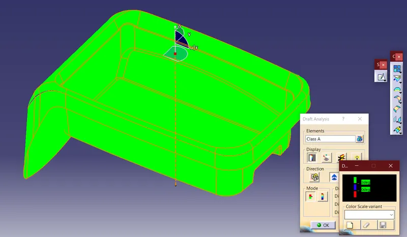
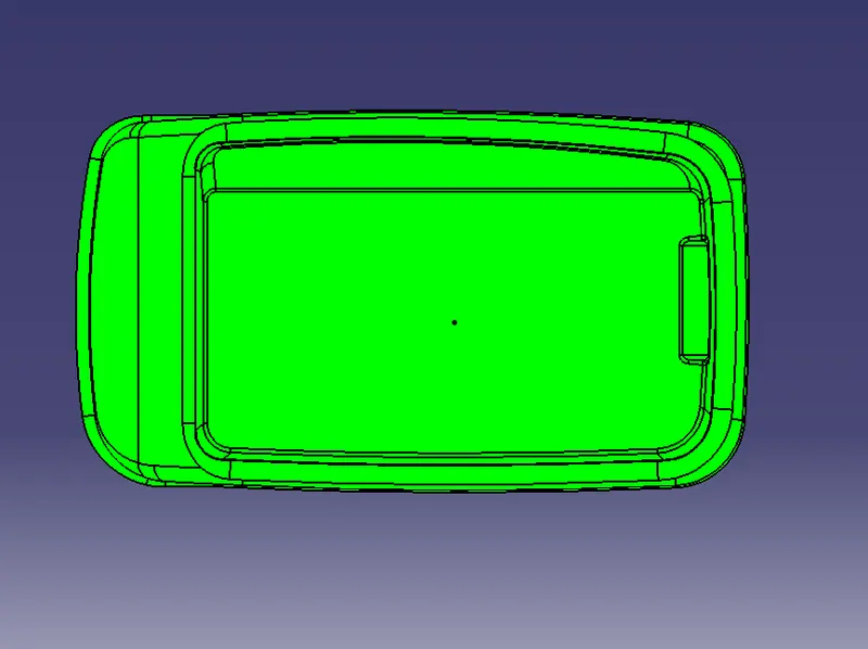
All faces of Class A are green which means they have draft of 3-degrees or higher. Hence, the tooling direction is verified and no changes are required for the tooling axis.
Class B surface: -
Class B surface is generated by extracting the planar elements, untrimming, extrapolating and joining them by trimming. This is done part by part starting from base and sides. For the fillets given to the faces the fillet faces are extracted from Class A, untrimmed and measured for the radius. Then maintaining the 2.5mm thickness gap between Class B and Class A the fillet is given to the faces.
Class C surface: -
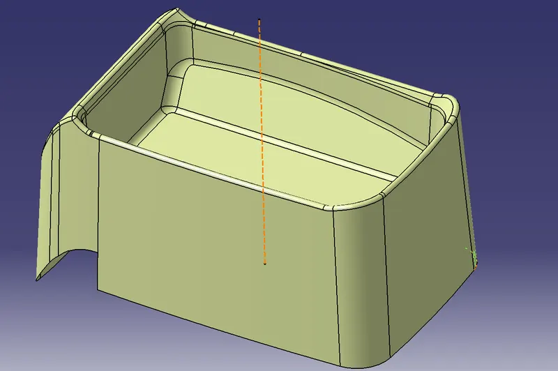
The boundary of Class A is extracted using boundary command and using that boundary Class C is created. The Class C surface is generated in reference to Class A and not in reference to the draft direction, for the coin holder. The angle between Class C and Class A is taken as 90-degrees.
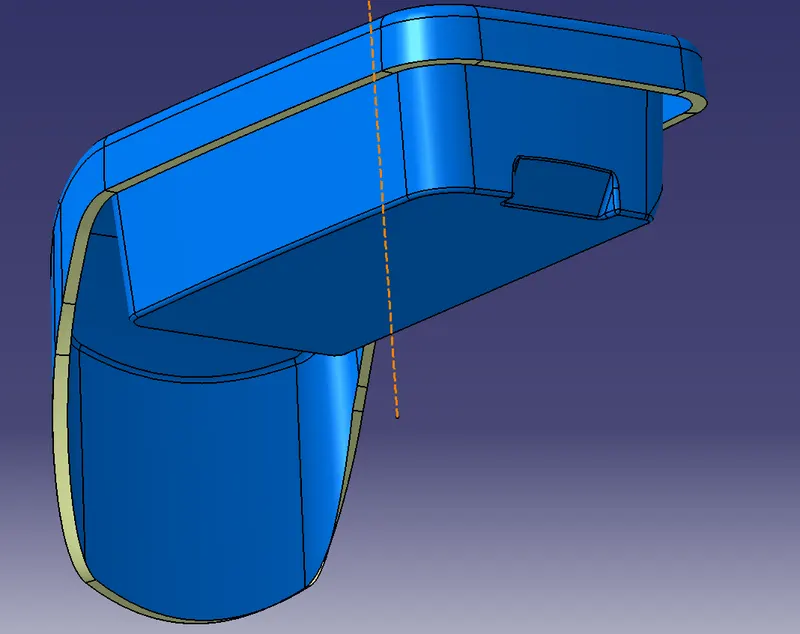
For the surface of the part body, Class A and Class C are joined and trimmed with Class B. The solid body is created by use of close surface command.
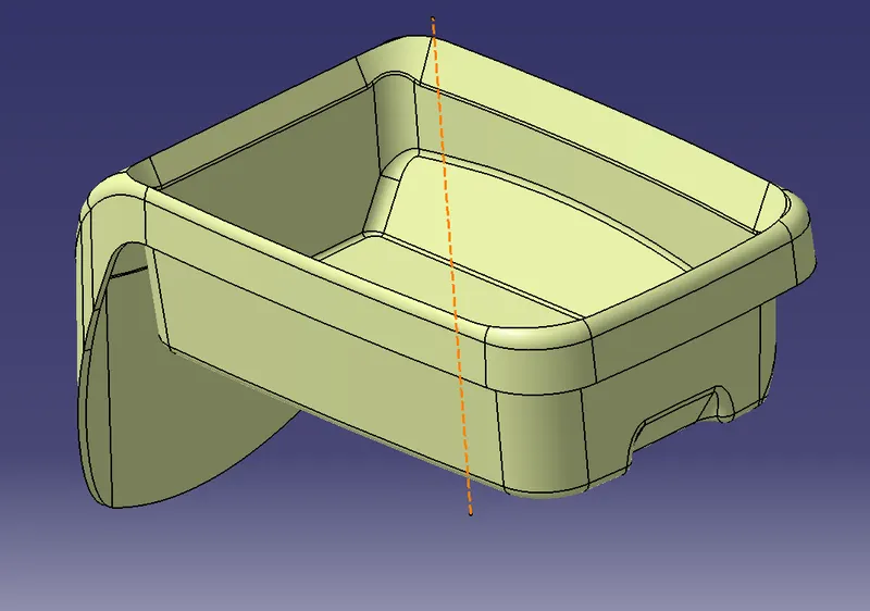
Plastic part draft analysis: -
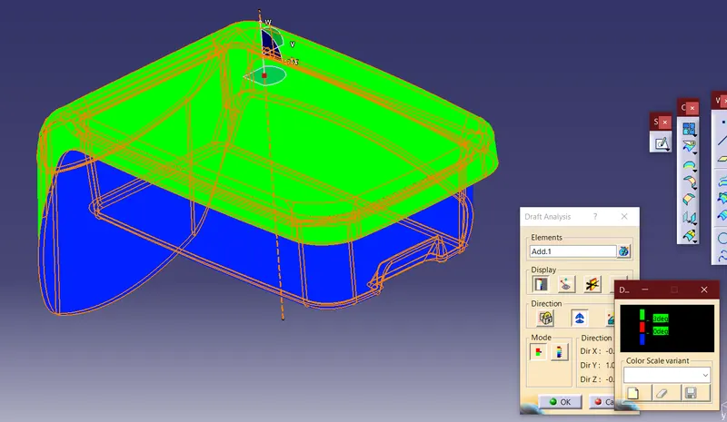
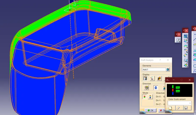
As can be observed clearly from the draft analysis of the plastic part, Class A is above the draft angle of 3-degrees. Class B and Class C are blue in colour which shows that they have negative draft. Negative draft is expected for the Class B surface. Class C has negative draft as it is generated using Class A as reference with 90-desgrees angle between Class A and Class C. This implies that Class C has normal direction which is parallel and opposite to the tooling direction. Therefore, Class C has a negative draft angle.
Various orientations of the part are given below
Isometric view
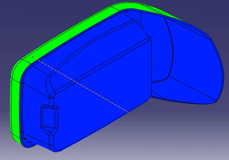
Front view
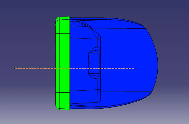
Top view
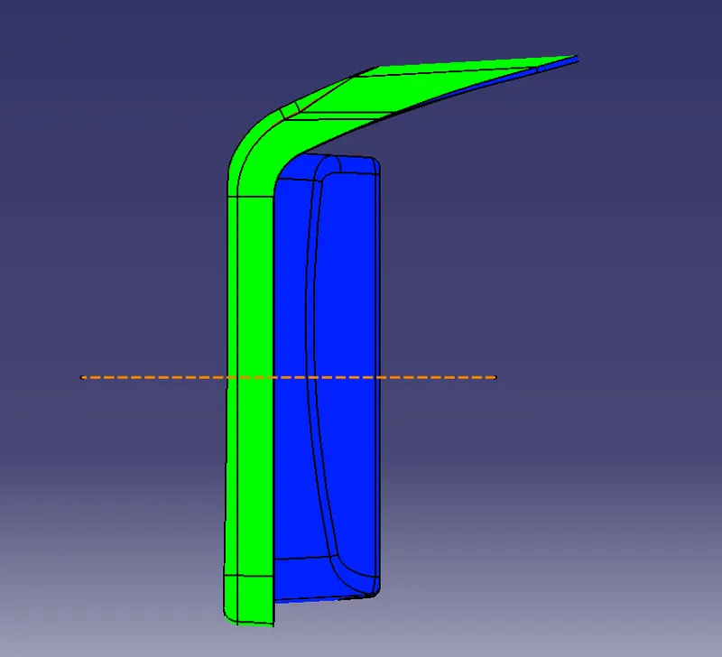
Left side view