Week 8 - Challenge 3 - Coin Holder Design
AIM
To create the Coin Holder Plastic component through the given Class-A surface.
REPORT
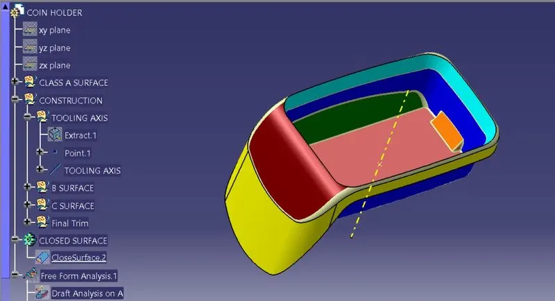
1. Creation of tooling axis
- First, class A surface is checked for the connectivity of the surface to ensure it is completely joined and there will be no gap between the surfaces. It is done using either boundary or join option.
- Once the connectivity is checked, we inpect the class A to determine the best possible axis for tooling.
- In this case since one of the wall is almost 90 deg and there are no other difficult geometries, we use direct method for creating tooling axis.
- Extract the base surface alone.
- Create a point on the centre of the surface using point option.
- Then using line command, a line is drawn along z axis which will be our tooling axis for this design.
2. Draft analysis on Class A surface
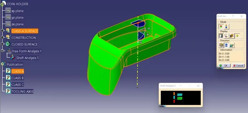
- Once the tooling axis is created, we conduct draft analysis on the class A surface to check the tooling axis is good or not.
- Select the draaft analysis command.
- Click on the compass option.
- Place the compass on the tooling axis to decide the drafting direction.
- Click anywhere on the class A, it displays the analysis results.
- Here we get green colour everywhere showing its a positive draft of above 3degrees which is good.
3. Creation of B surface
- We divide the Class A into different sections and work on them to create Class B .
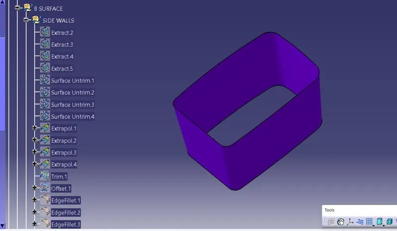
- First we take the side walls and extract them.
- Untrim all the sides
- Extrapolate them so much so that they intersect.
- Trim all them together.
- Then we offset them outside by 2.5mm
- Fillet the corners
- Then we extract the base surface.
- Same as above, we untrim them and extrapolate till it intersect the side walls.
- Offset them by 2.5mm.
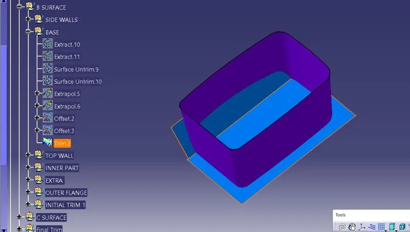
- Then we extract the top wall and do the same steps as above.
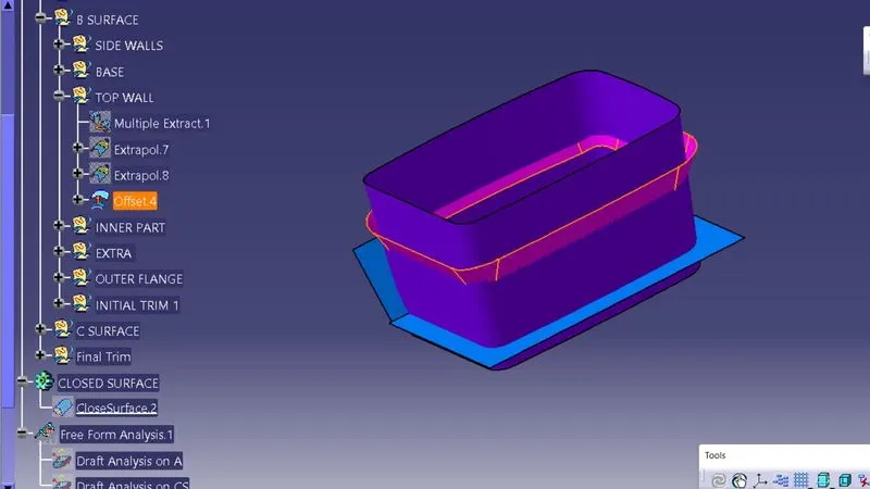
- Then we extract the small inner part of the bottom surface and untrim them.
- Extrapolate till all of them intersect.
- Trim the walls of inner part.
- Offset them inwards.
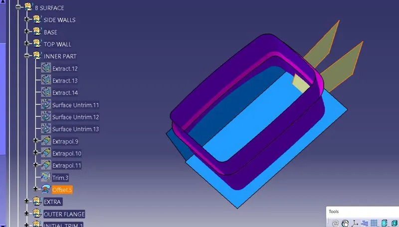
- After this we will first trim the side walls and base surface together.
- Then we trim the resultant surface with the top wall.
- This resultant surface is trimmed wth the inner part.
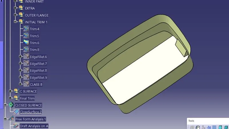
- Then after this, we take the outer flanges and extract them.
- We extrapolate the outer flanges and offset both of them inwards.
- Then we trim both these outer flanges together.
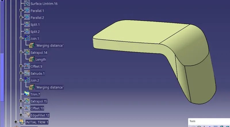
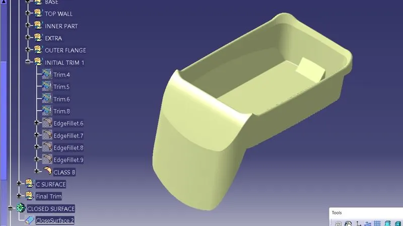
- After this we trim the outer flange with the initial trim.
- We fillet all the edges to get our B surface.
4. Creation of C surface
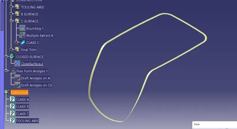
- For creation of C surface, we take the Class A and using boundary option extract the boundary of A.
- Then we extract the adjecent surfaces to these boundaries.
- Then we take sweep command and draft it along the surface at 90 deg.
5. Final join
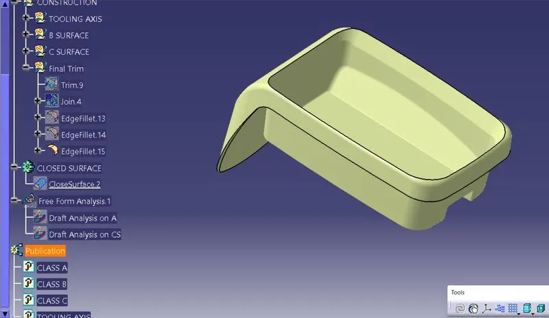
- Now we first trim the B and C surface together.
- Then this surface is joined with the class A surface.
6. Closed surface
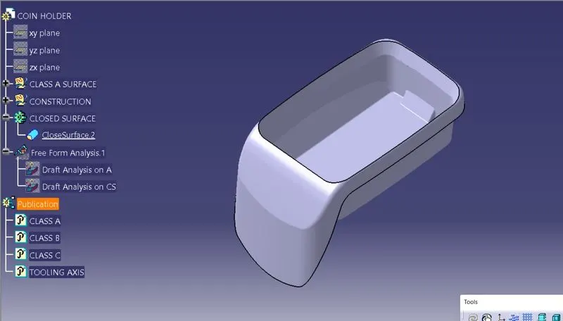
- Once the final join is done we switch over to part design and using the option closed surface we create the final plastic component
7. Draft Analysis on Final component
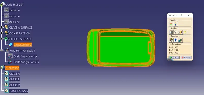
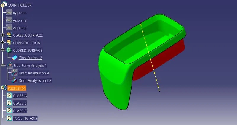
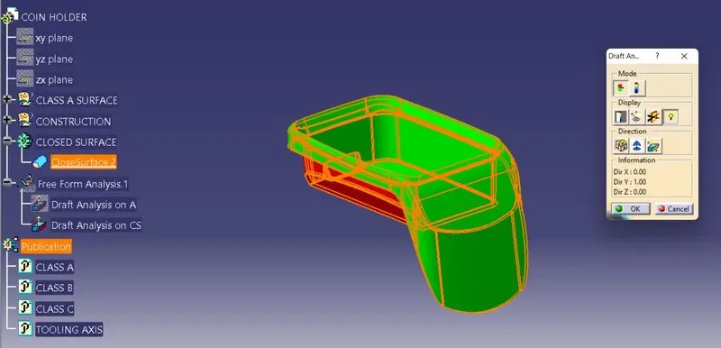
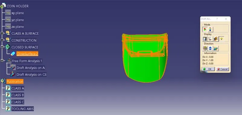
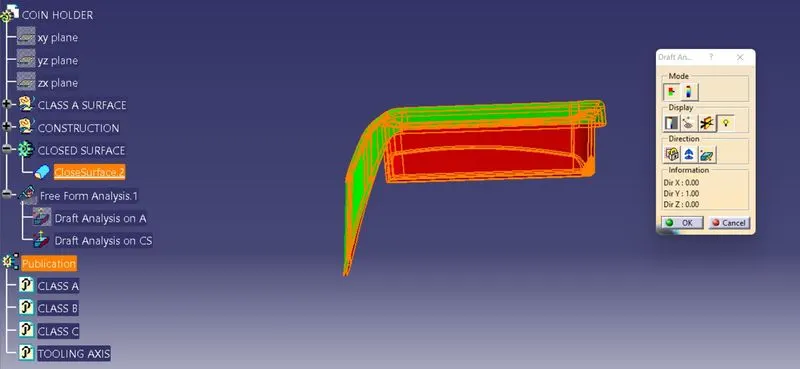
- Similarly as done for A surface, we do draft analysis on the final component.
- From the resulta we can see that it is showing positive draft on core side.
RESULTS
1. ISOMETRIC VIEW
2. FRONT VIEW
3. SIDE VIEW
4. TOP VIEW