Week 8 - Challenge 2 - Switch Bezel Design
Aim -
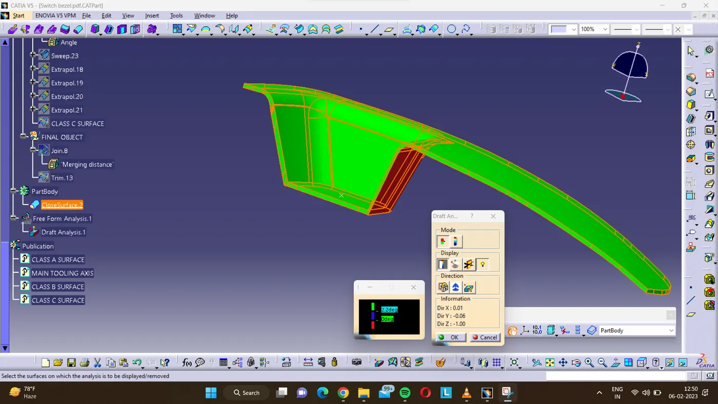
Create the Switch Bezel Plastic component through the given Class-A surface. To begin with, the tooling axis for the given Class-A Surface should be created meeting the requirements of the draft angle and at the end perform the Draft analysis on the model.
Take the Thickness of the component to be 2.5 mm
TOOLING AXIS -
- In order to obtain the proper draft analysis tooling axis is required and the following steps show how it is done.
- As this component has 1 hole from where the tooling axis can be generated, however it does not have proper 4 walls to generate it. In this case, an approximation is made in order to obtain the tooling axis.
- First by using the two side walls a dummy axis is made. As it is known that the draft angle is 3 degrees, the second axis is taken as a 3 degrees to the given wall and using these two axis the tooling axis is made.
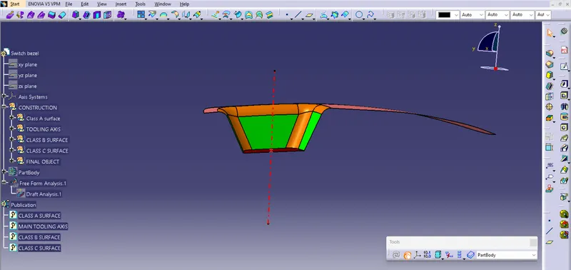
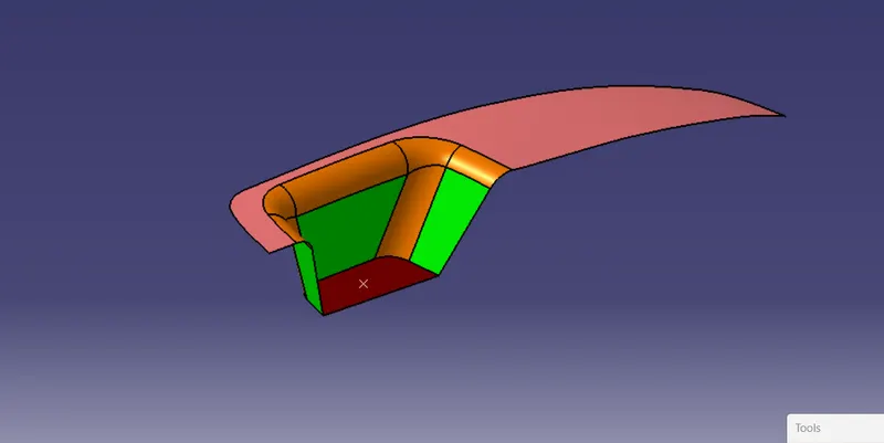
CLASS A SURFACE - Class A surface is given by the challenge section.
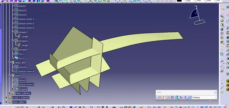
CLASS B SURFACE - For making Class B surface we have to choose not fillted faces and extract them from class A and after that, we have to untrim and extrapolate as well after all faces intersecting with each other we trim them and get the class B surface,After getting class B we offset it to 2.5 mm and give it required fillets process shown in figures -
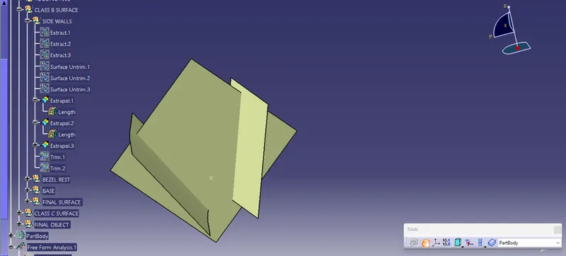
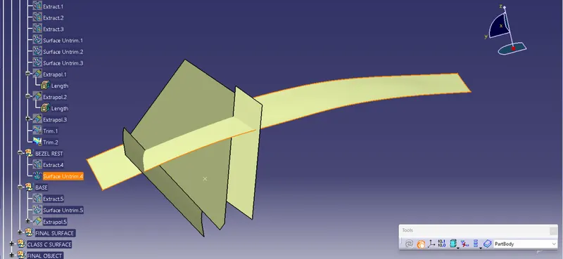
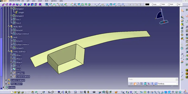
After giving the required fillets -
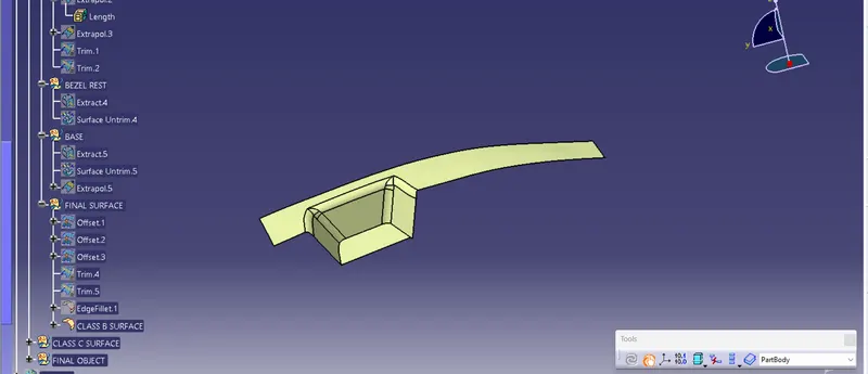
CLASS C SURFACE - Class C surface is the surface that joins Class A and Class B So to make this we have to take multiple extract of the boundary of Class A and give sweep command to it with the draft direction.
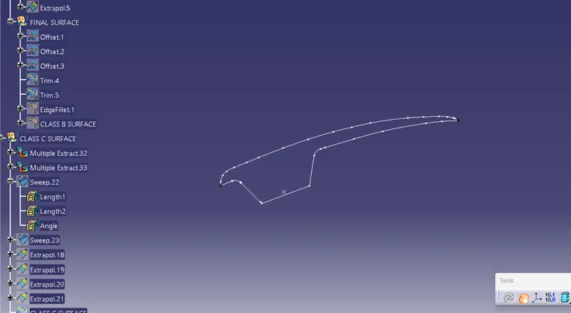
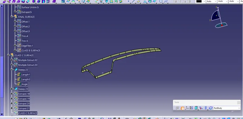
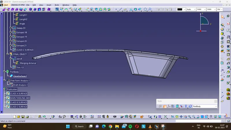
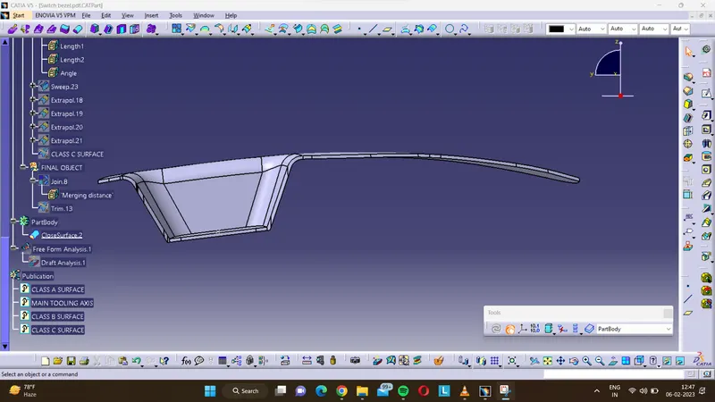
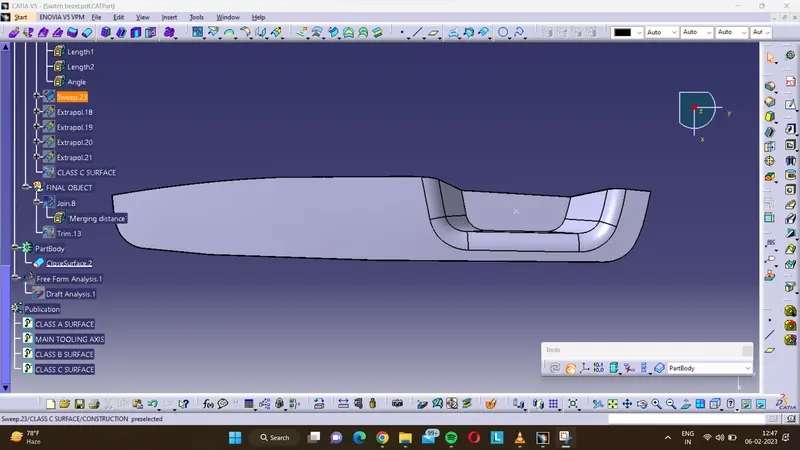
Final surface - For the final surface, we have to join Class A and Class C first and after that, we have to trim the join with Class B.
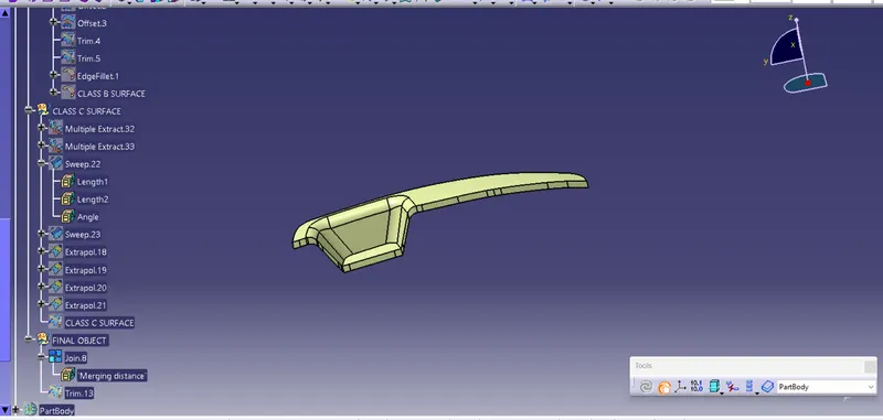
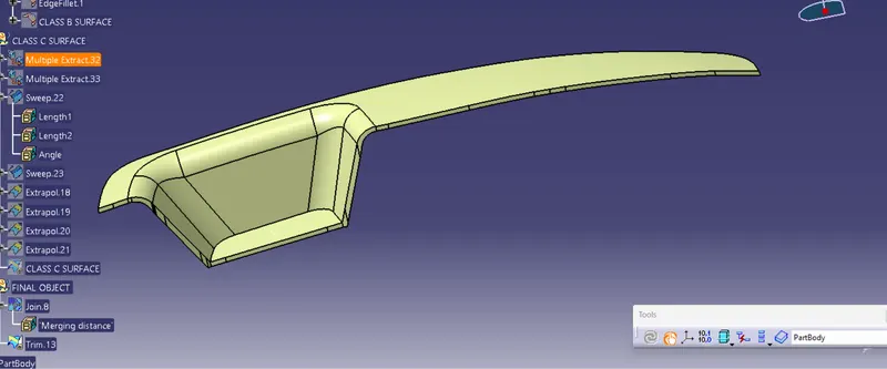
Solid-body -
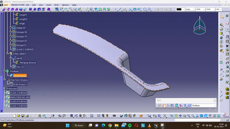
DRAFT ANALYSIS -
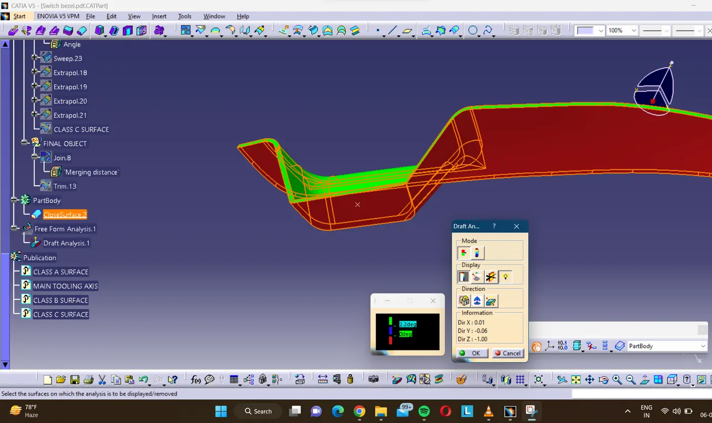
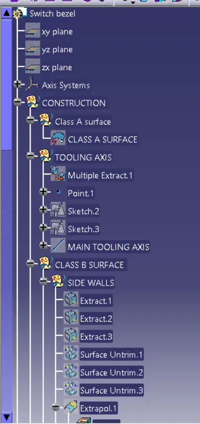
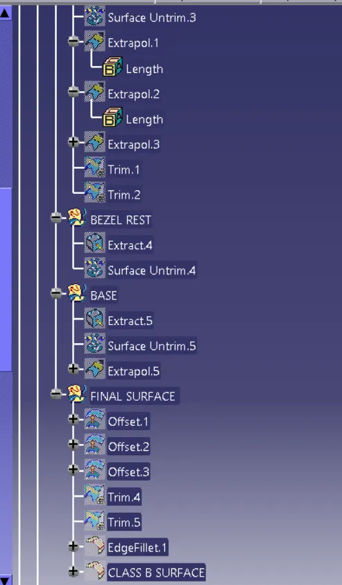
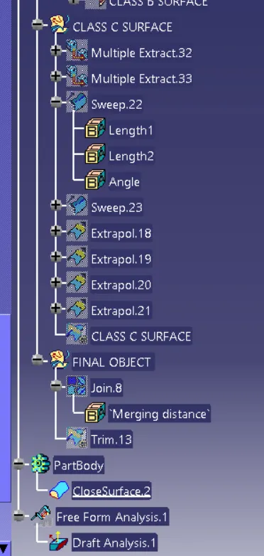
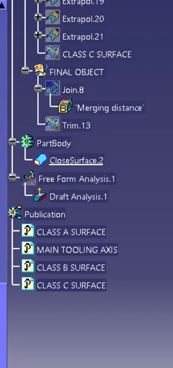
TREE STRUCTURE -