Week 8 - Challenge 2 - Switch Bezel Design
AIM
To use the provided Class-A surface to make the Base Bracket Plastic component. The tooling axis for the specified Class A Surface should be developed first, according to the demands of the draft angle, and then the model should undergo a draft analysis.
Procedure
At First, Check the Class A Surface's connection. Using the join command, make sure there are no gaps between the components. We may visually inspect it or use the boundary command to do so. One outside and two inner circular limits make up its three borders. So, the initial check is finished.
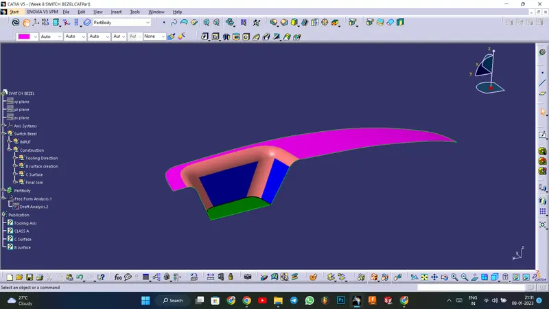
Find the component's tooling axis. The opening of the cavity or of the mould constitutes the tooling axis. Look carefully to determine the ideal tooling axis. Verify each axis. X is feasible, but it is costly, and Y is not feasible. The optimal tooling axis is z.
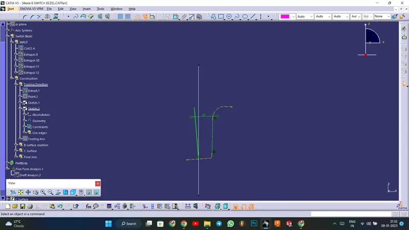
Creating a Tooling axis along z : Using the bisecting line method, the tooling axis is drawn.
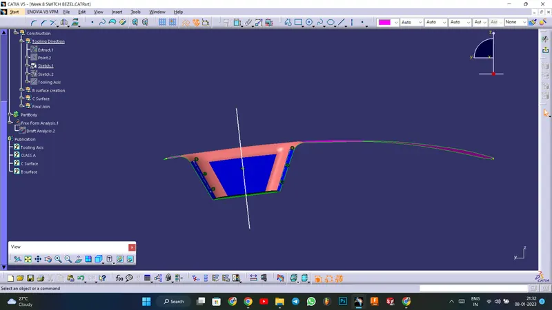
BISECTING LINE METHOD: Using a dummy tooling axis, the bisecting line method is essentially used to identify the correct tooling axis. When using the bisecting line method, a line is utilised to either bisect the two lines or indicate an error, indicating that the two lines are parallel to one another. We intersect the surface with the appropriate plane to determine whether or not the surface is toolable. This produces a drawing with two lines, which we can then bisect to produce a third line at the intersection of the two lines. If there is no plane at the other side draw the line with appropriate angle(6 degree), so that it satisfies the draft angle
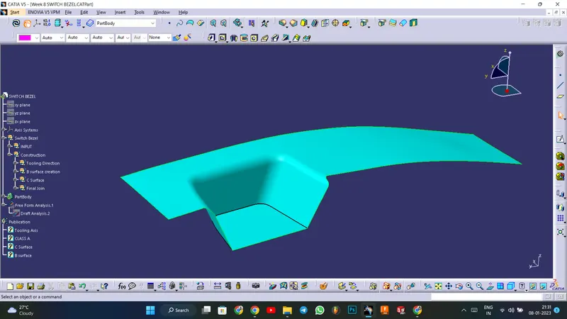
Creating Class B Surface: Utilising the extract option on the Class A surface to firstly extract the two draft surface and the base. Extrapolate is then used to extend the length. Trim the surfaces now to the appropriate surfaces. Then, offset the surface to obtain the necessary thickness. Similarly, obtain the flat surface and offset it to the appropriate value. And now, trim to get the desired surface. Fillet the surface now to the necessary amount.
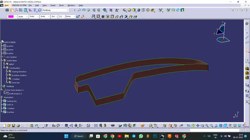
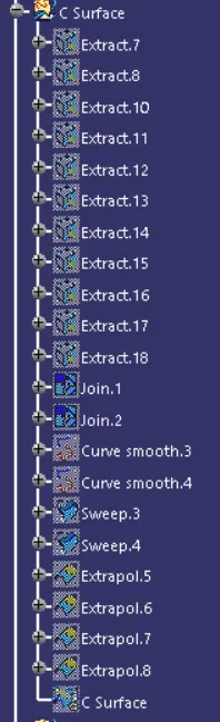
Creating Class C Surface: At first extract the boundaries of the Class A surface using multiple extract and sweep it along the tooling axis using sweep with draft angle option in sweep.
Final output : Now trim the Class A , Class B and Class C surfaces to get the desired output. and make it as a solid component using the close surface feature in part work bench
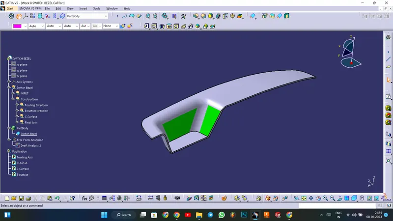
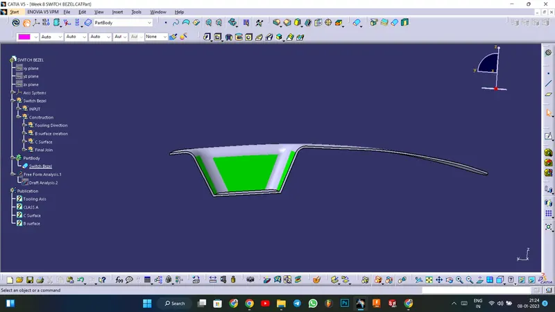
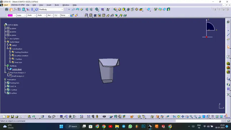
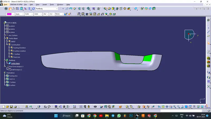
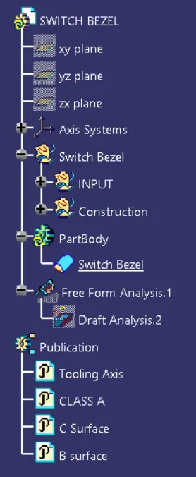
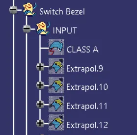
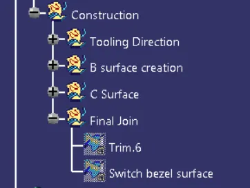
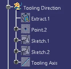
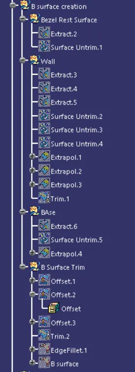
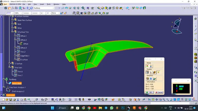
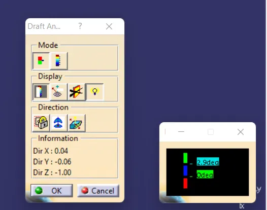
Draft Analysis : Use the Featured Draft Analysis tool in the tools to now analyse the draft. After locating the compass and aligning it with the tooling axis, click on the lock symbol after aligning, and then click again on the surface after opening the draft analysis tool box.