Photo Realistic Rendering
MODELLING AND RENDERING OF AMERICAN CHOPPER
OBJECTIVE :
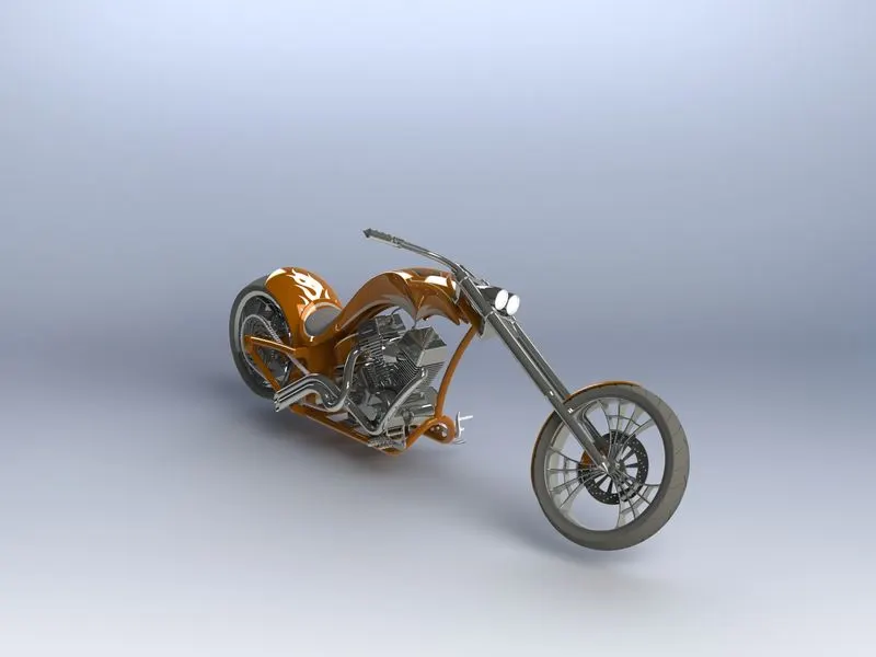
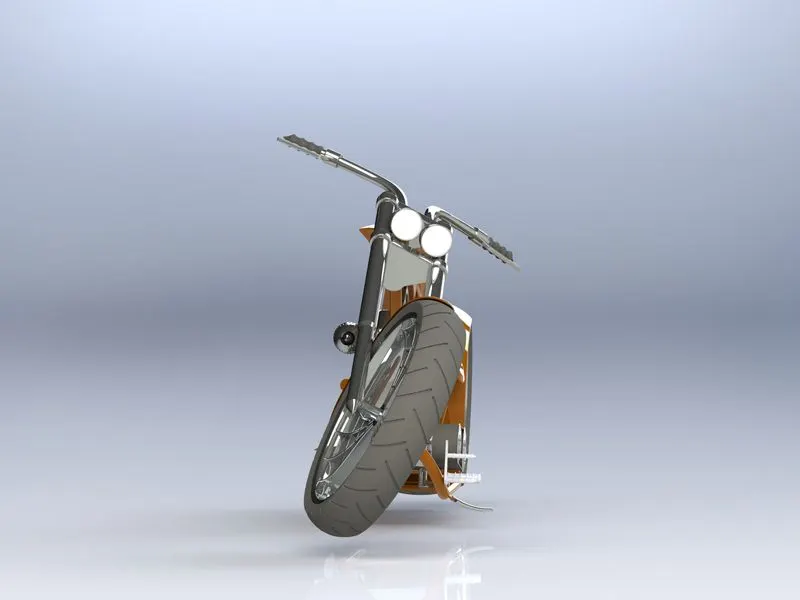
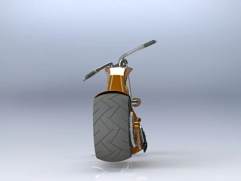
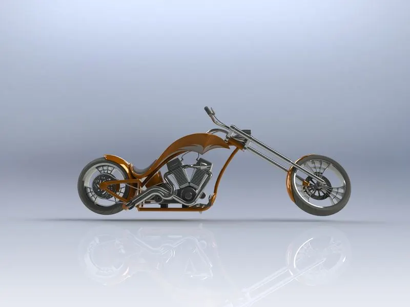
To model every part of the American chopper and make an assembly of it and to create photo-realistic renders of the American Chopper using Solidworks.
INTRODUCTION :
This project is about modeling parts of an American chopper and assembling it using Solidworks and rendering the 3D model using Solidworks Photoview 360 or Solidworks visualize.
DESIGN METHODOLOGY :
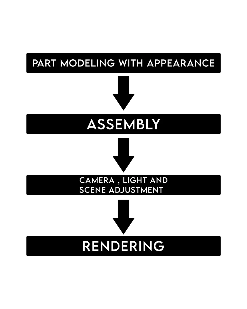
FLOW CHART :
PART MODELING :
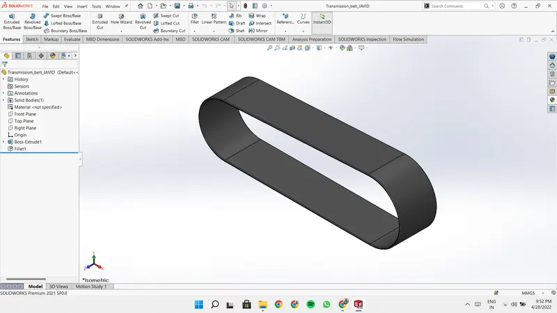
- Transmission Belt: Belts are used for the power transmission from one shaft to another. For modeling this belt, I drew the 2D sketch and extruded it into a 3D model, and gave a Matte Rubber appearance for this Belt.
- Kickstand: kickstand holds the whole motorcycle from falling in a stationary position.
For modeling this kickstand stand, I drew the 2d sketch first and extruded it then used the cut extrude feature to make the mounting and used the dome feature at the end and added some fillets.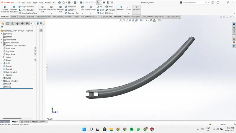
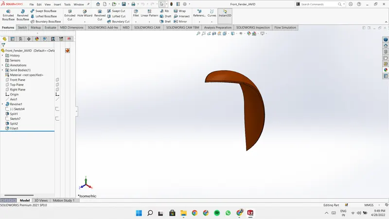
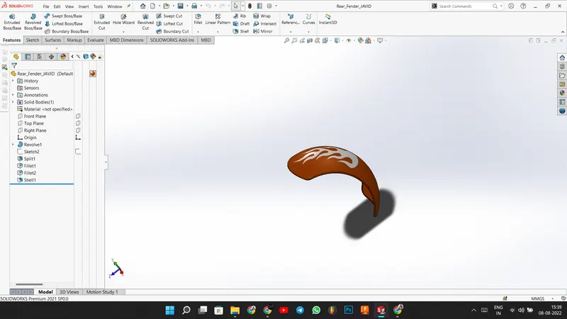
- Front and Rear Fender: fender is used to prevent the motorcycle from mud, dirt, and even water which are spread by the rotation of the tier.
For modeling the fenders I used the 3point arc and revolve boss feature to create the 3D model. then used the split tool to remove the unwanted parts and finally added some fillets.
I gave Siena paint appearance to the fenders and added some decals to the rear fender.
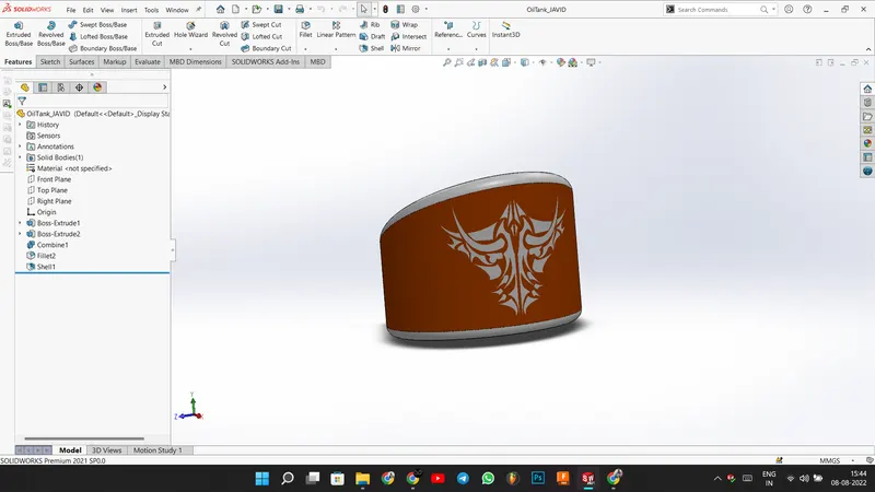
- Oil Tank: It stores the oil for lubrication and cooling.
For modeling this oil tank, I created two boss extrudes, and then I used the Combine feature to get the required shape and added some fillets at the edges.
I applied the same Siena paint to this also and added a decal to it.
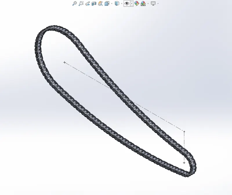
- Chain: The chain is used for power transmission from the engine to the rear wheel.
To model the chain I outlined first and using the blocks feature I created 2 sketches and used the curve-driven pattern and make some little adjustments and then used the mirror feature to complete the model. Applied chrome appearance for the chain.
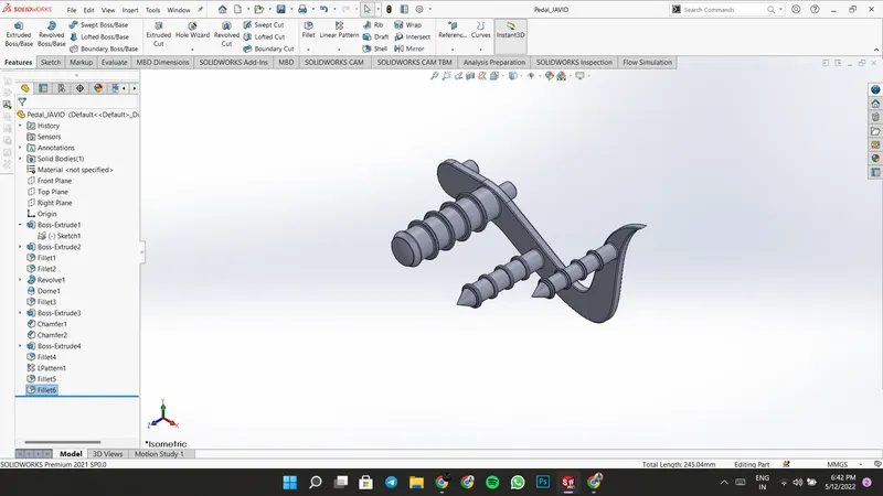
- Pedal: Pedals are used as a rear brake and gear changing lever and for resting the foot. I used various features like Extrude boss, Revolve boss, Dome, Fillet, Chamfer, and Linear pattern to model this Pedal.
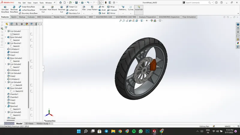
- Front Wheel: Front wheel helps for the movement of the Chopper, It consists of Rim, Break Disk, Break Caliper, and Tire. Rim is modeled using Revolve Boss, Extrude Boss, Cut Extrude, Revolve Cut, and Circular Pattern and Combine feature. Break Rotor is modeled using Extrude boss, Cut Extrude, and Circular pattern. Break Caliper is modeled using Extrude Boss and chamfer. The tire is modeled using Revolve Boss and Cut extrude features.
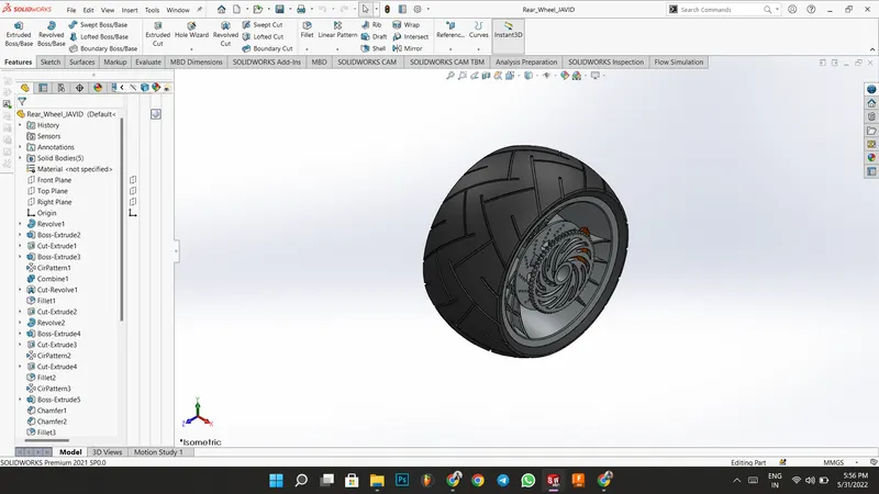
- Rear Wheel: Rear wheel is used for the movement of the Chopper. It is designed in the same way as the front wheel but the sprocket is an extra component in this. The sprocket is connected to the engine through a chain drive. Sprocket is modeled using extrude boss, extrude cut, and circular pattern features.
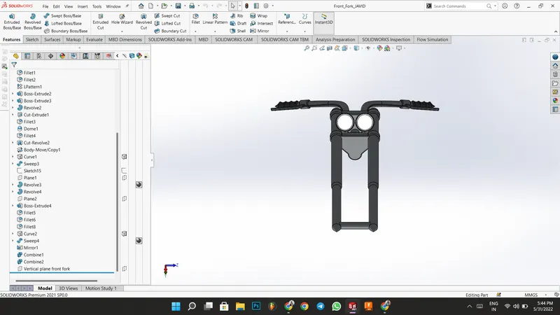
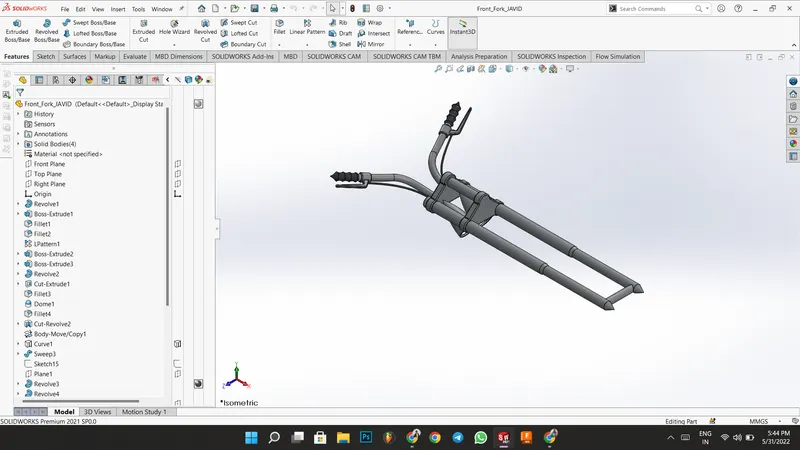
- Front Fork: Front Fork helps in the steering of the Chopper. It consists of a Headlight and a Shock absorber. The front fork is mirrored part and modeled using Revolve Boss, Extrude Boss, Extrude Cut, Revolve Cut, Sweep Boss, and Projected Curve.
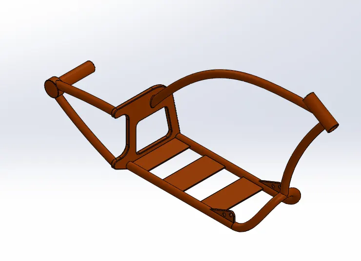
- Chassis: The chassis is the main frame of the Chopper which connects all the components of the Chopper. I modeled this using projected curves, sweep boss, extrude boss, revolve boss, Split, and Combine features. Added some Fillets For Smooth Edges.
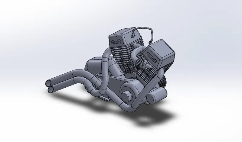
- Engine: The engine is the power source of the Chopper. The engine is modeled using Extrude boss, Cut Extrude, Chamfer, Patterns, Split, Combine, Projected curves, and Sweep Boss.
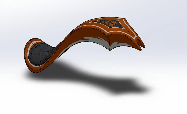
- Gas Tank: It helps for storing fuel for running the engine. The engine is modeled using the Projected curve, Boundary Surface, Sweep Surface, Trim Surface, Surface loft, surface knit, shell features and finally added some fillets. Some decals are also added.
ASSEMBLY :
First opened all the parts of the Chopper.
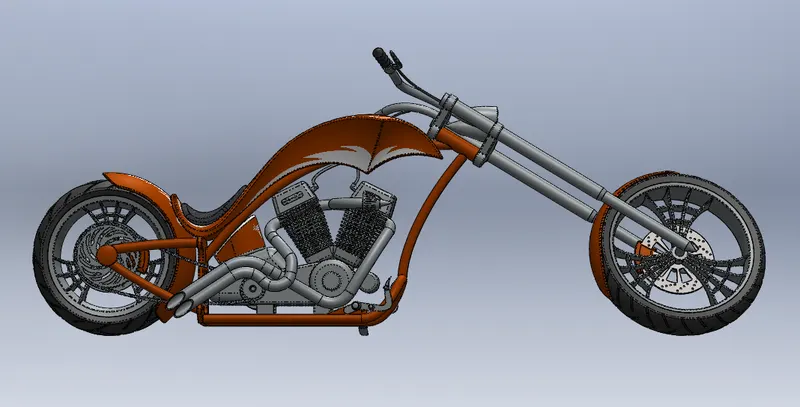
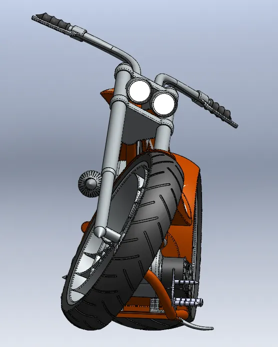
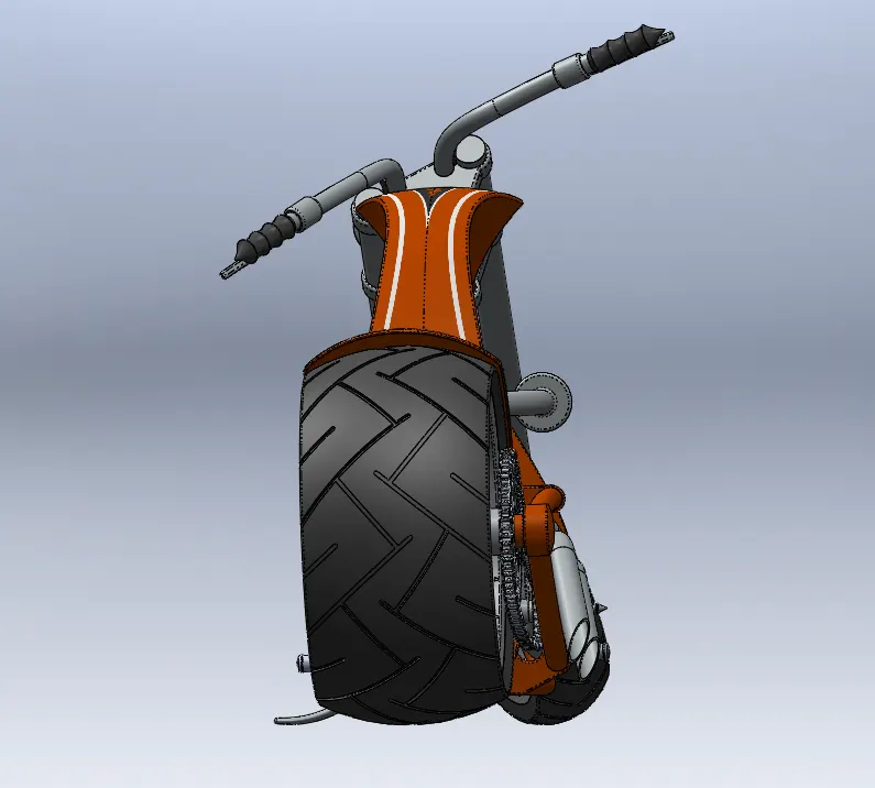
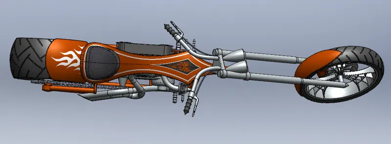
Then inserted the Chassis, engine, belt, kickstand, oil tank, rear wheel, chain, gas tank, front fork, front wheel, front fender, and rear fender.
Used some mates like coincide, angle, concentric, and tangent to assemble these components together.
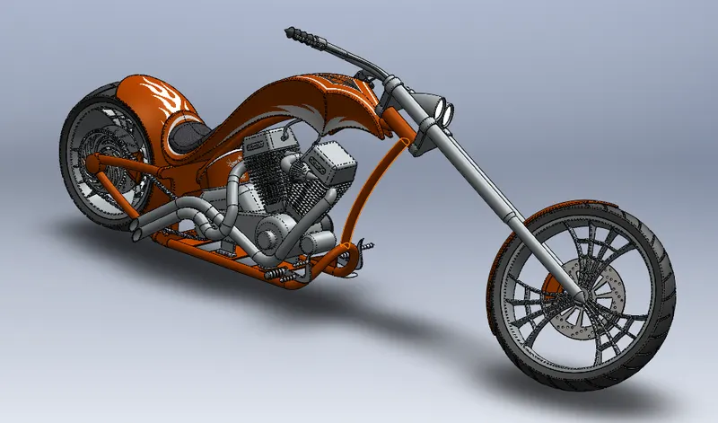
LIGHT: While rendering lights are very important for the exposure of the Chopper and the shadow. We can add different types of light in Solidworks like Directional Light, Point Light, Spot Light, and more importantly Sun Light.
SCENES: We can set a background image and HDR image for the reflections on reflecting surfaces.
CAMERA: we can add a camera view to the chopper where we can the Focal length of the camera, and depth of field of the camera. We can add multiple camera views.
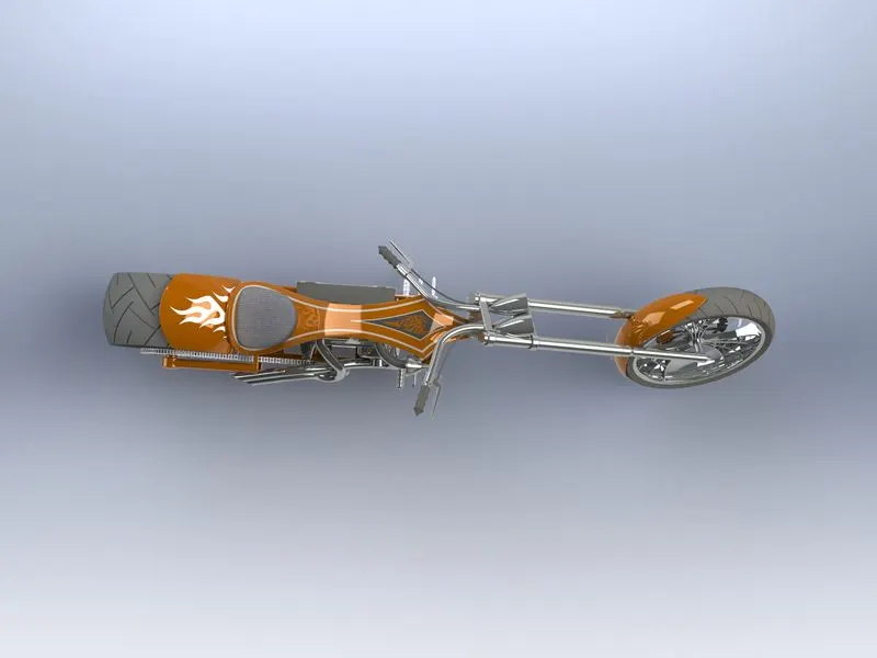
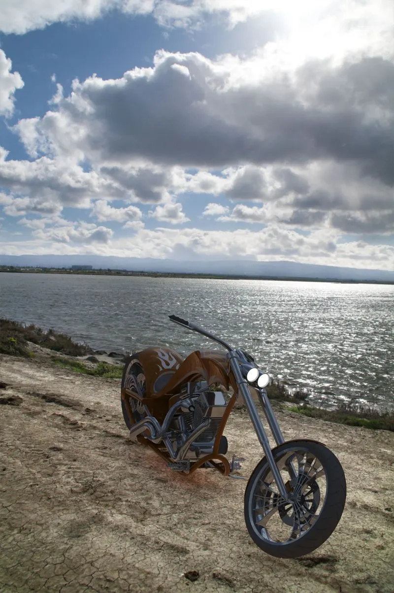
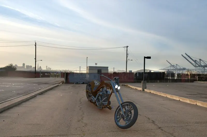
RENDERING: renders give you a realistic view of the Chopper. Renders are done both using Photoview360 and SolidWorks Visualize.
CONCLUSION :
From this Project, I learned most of the Solidworks tools for Part Modeling, Assembly, and Rendering and got familiar with the Solidworks interface.