Week 8 - Challenge 2 - Switch Bezel Design
Design of switch bezel with a thickness of 2.5mm:
The given class-A surface is shown below.
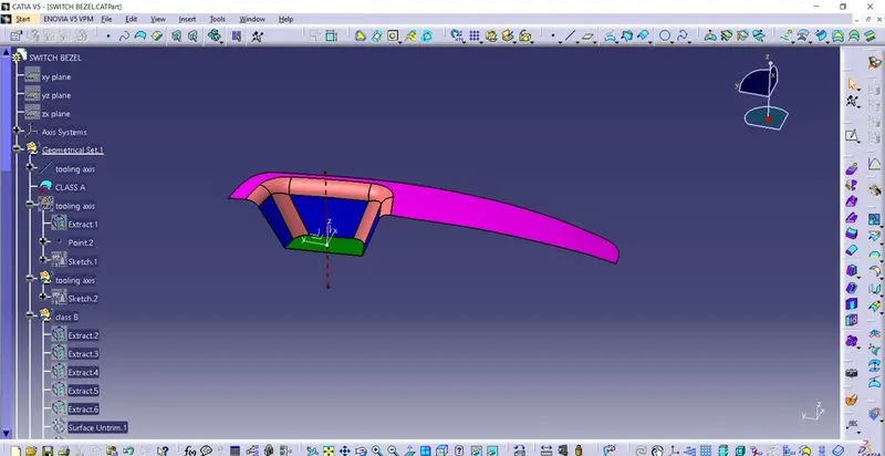
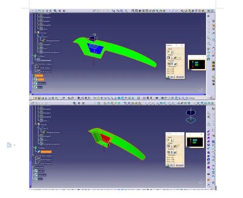
The draft analysis of the given class-A surface. The blue patch indicates the minimum of 3-degree draft angle is not satisfied with the created surface.
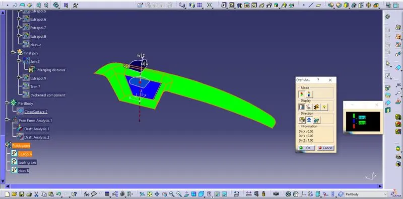
Tooling axis:
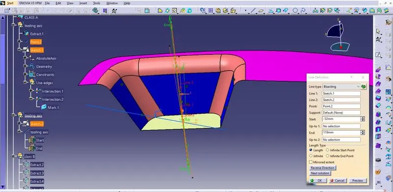
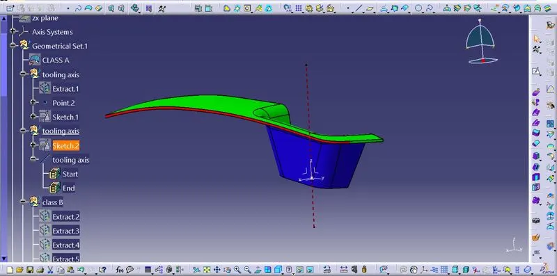
The tooling axis is created using the bottom surface as the reference. Select the bottom face and extract the surface. Now insert a point and using the point insert an axis system. Now using intersect option generate the boundary of the class-A surface. Make the boundary as a construction element and draw two lines on the edges as shown in the figure. Using these two lines, generate a centerline using the bisecting option.
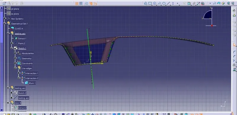
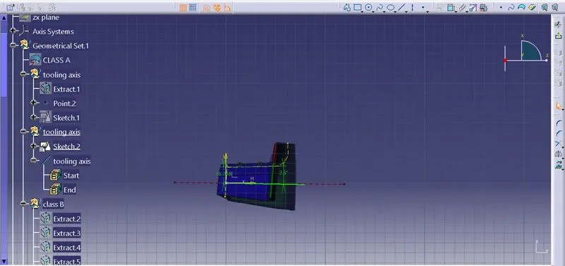
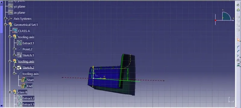
Now we have a tooling axis with respect to surfaces that are on either side of the tooling axis. But there is also another surface on the Z-axis and we need to consider this surface to create the tooling axis. Now insert another geometrical set, and use the positioned sketch to draw the sketch. Using the intersect option generate the boundary and now draw the line parallel to the boundary as shown in the figure. Draw a line on the boundary parallel to the centre line. Define the angle between the two lines. I have used an angle of 3.5 degrees.
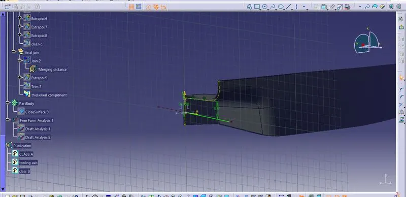
Now, we have two lines from sketch-1 and sketch-2. Using Bisecting option insert a line bisecting the two lines which we created and the point as the reference. It generates a line that bisects the two lines. Now we have our final tooling axis.
Class-B surface:
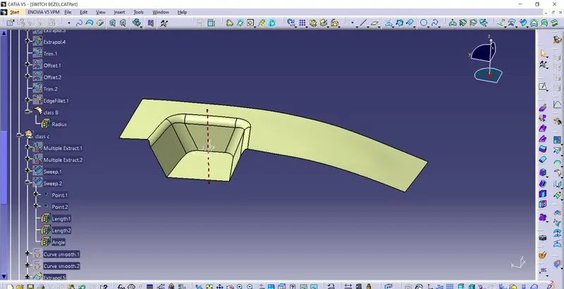
As we created the tooling axis, we need to create the class-B surface using the class-A surface. To create the class-B surface we use extract, untrim, extrapolate and trim options. Select that faces of the class-A surface which are not filleted. select each face, extract the face, untrim it, extrapolate the surface, and trim with the other faces. after trimming offset the whole surface to a distance of 2.5mm because we need a thickness of 2.5mm. The created class-B surface is shown in the figure.
class C:
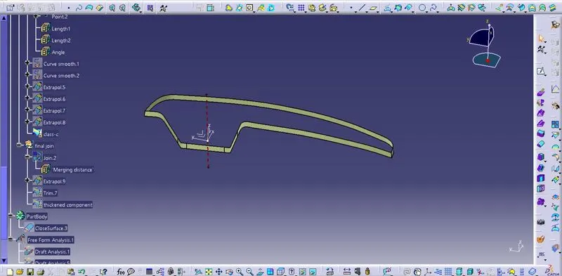
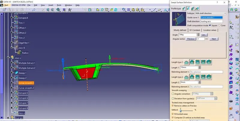
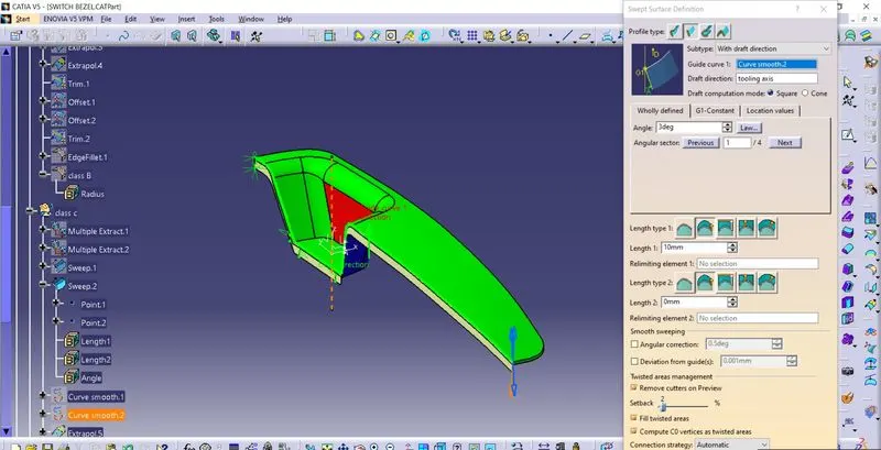
To create the clas-C surface we require the boundary of the class-A surface. Use the multiple extract option and select the boundary of the class-A surface. I have divided the class-A surface boundaries into two parts to create the sweep easily. Select the first boundary and insert the sweep command, using the draft option, and provide the draft angle as 3-deg. Select the boundary as the guide curve and the draft axis as the tooling axis. The created class-C surface is shown in the figure.
Join class-A and C:
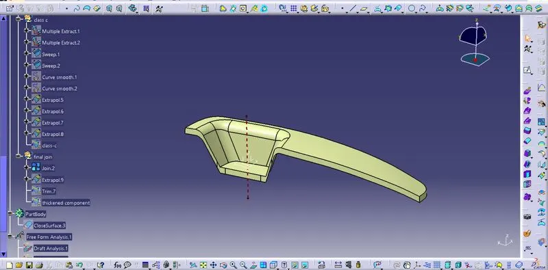
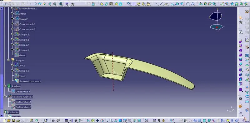
After creating the class-C surface unhide the class-A surface. join both the surfaces using the join command. The output of the joined surface is shown below.
Final component:
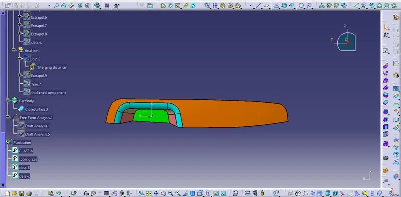
Once we have the joined surface of class-A and class-C surfaces, unhide the class-B surface. Now use the trip option to trim the excess portion of the class-B surface. After trimming we get the final component of the required thickness of 2.5mm. The output image is shown below.
Draft Analysis:
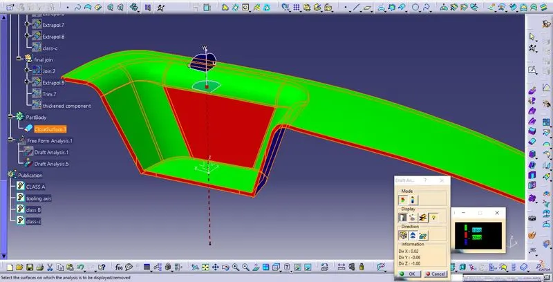
Class-A surface: The draft analysis of the class-A surface with respect to the tooling axis with the minimum draft angle of 3 degrees. The blue colour region which is visible in the image is not satisfying the 3-deg draft angle.
Draft analysis of thickened component:
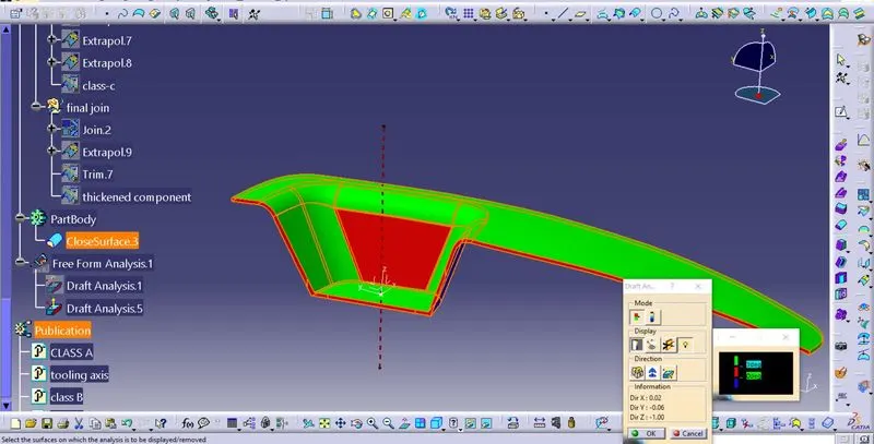
Sweep angle: We tried altering the sweep angle of the class-C surface from 2.5 to 3-deg angle but the result was the same. The red colour patch which is seen in the below image has not been changed even with the change in class-C surface draft angle.
Tooling axis angle:
One more way that we have tried is changing the tooling axis angle. from 2.5deg to 5deg angle we have tried each and every iteration but the middle surface which is in red colour has not been solved. The iteration images are shown below.
2.5deg draft
5deg draft
3.5 deg draft
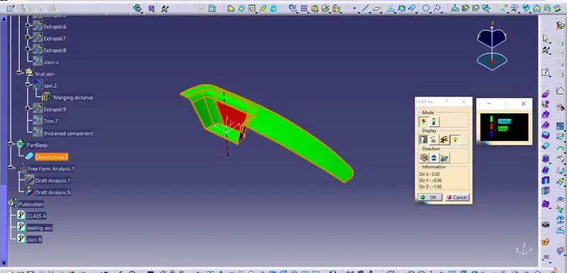
As we can see the tooling axis with a 3.5deg angle and the draft angle of 2.8degree gives us the optimum result.
Draft angle:
The draft angle of 3deg has shown red colour region at the middle surface and on the thickness. so we reduced the angle to 2.8deg, this has removed the red colour region at the thickened region but the middle surface has not been solved. The images have been shown below.
- Screenshots of the Draft analysis report for both the given Class-A surface and the final plastic component
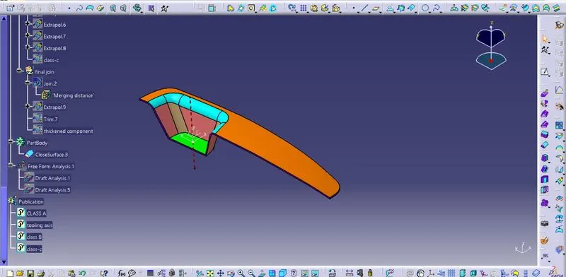
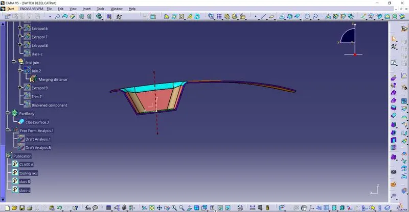
- Screenshots of the solid model with the proper colour code of the draft angle in various orientations (Isometric, Front, Side, and Top View).
Publication:
Conclusion: After creating the class-B and class-C surfaces we have achieved the thickened component. After performing the draft analysis we found that the class-A surface has to be modified to satisfy the min 3-deg draft angle.