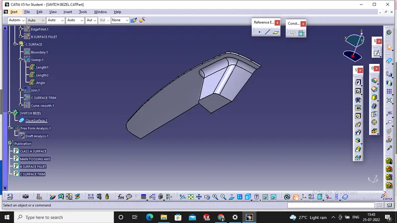
Week 8 - Challenge 2 - Switch Bezel Design
Objective : -
To create Switch Bezel using CATIA V5 SOFTWARE as per automotive OEM standard and Create B Class and C Class and tooling axis. As well as converting close surface into the solid inside the part workbench and provide the thickness of 2.5 mm, and last performing draft analysis to verify the creation of the tooing axis and C Class surface.
Design Methodology steps : -
- A Reference point is created along the surface zero and new axis system is created.
- The X direction along the Class A and Y direction along the class A were used to create Tooing direction.
- Finally the tooling axis is created by bisecting the two lines and it published. Class A Surface as input using surface operation cammands Class B id developed.
- The tooling Axis determines the direction of Class C boundary swept the draft direction.
- When viewing from the tool axis normal all the parts that are drafted should be visible so it gives an rough idea to determine product manufacture in injection molding.
SCREEN SHOTS OF OUTPUT : -
SHOT 1 :-
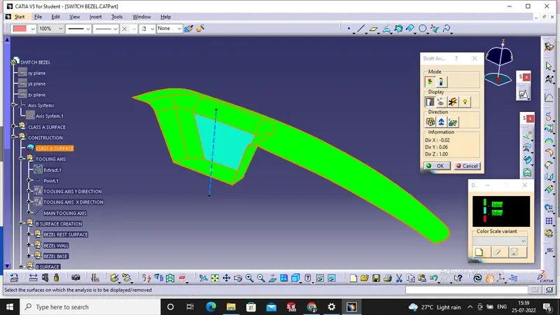
SHOT 2 :-
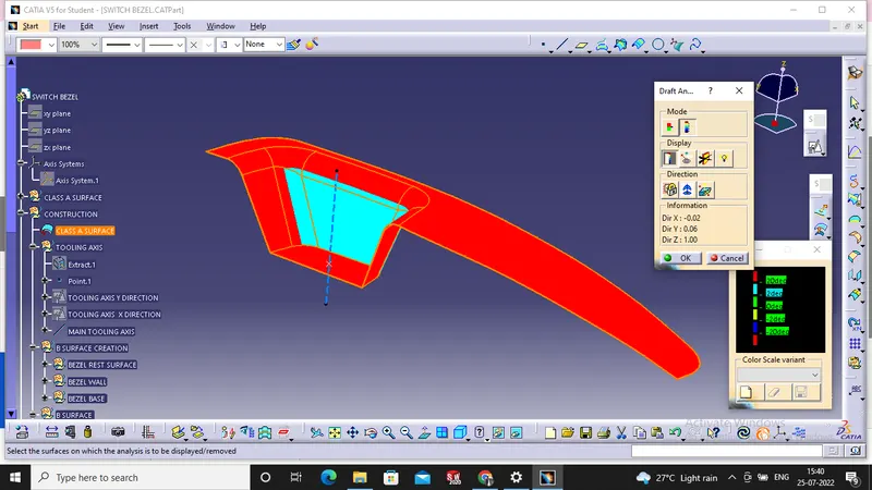
SHOT 3 :-
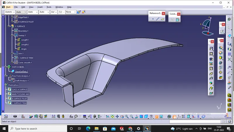
SHOT 4 :-
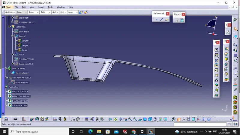
SHOT 5 :-
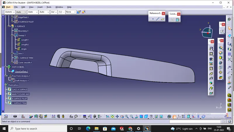
SHOT 6 :-