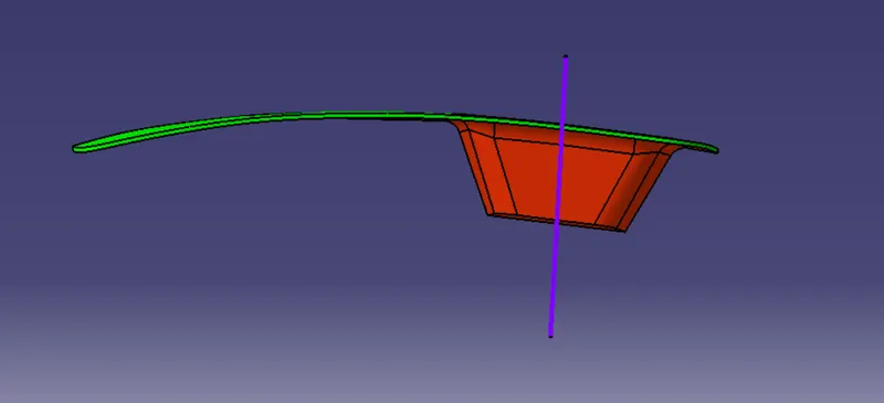
Week 8 - Challenge 2 - Switch Bezel Design
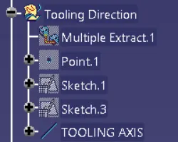
STEP 1- CREATION OF TOOLING AXIS
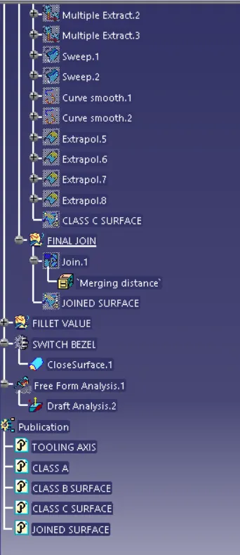
- A new axis system and reference point are established along Surface Zero.
- Tooling direction was created by using the X direction and Y direction along Class A.
- After cutting the two lines in half, the Tooling axis is formed and published. Using surface operation commands, take a Class A Surface as input. Class B has been created.
- The Class C boundary swept with draft direction is determined by the tooling axis.
- All drafted parts should be visible when viewed normally from the tooling direction to provide a general concept of how an injection-molded product is manufactured.
STEP 2- CREATION OF CLASS B SURFACE
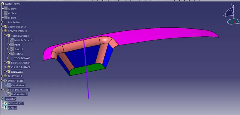
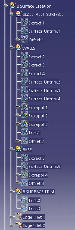
- Designing B surface for the input, which is typically the surface where all engineering considerations and support constructs are made, is the following phase.
- In CATIA, surface operations are used to create the B surface, which differs from Class A in that its dimensions are proportionate to the part's thickness.
- The thickness of the component, 2.5mm, is offset from the input by the B surface of the switch bezel.
- The bottom skin of the portion is made up of the B surface, which is extrapolated in relation to the A surface.
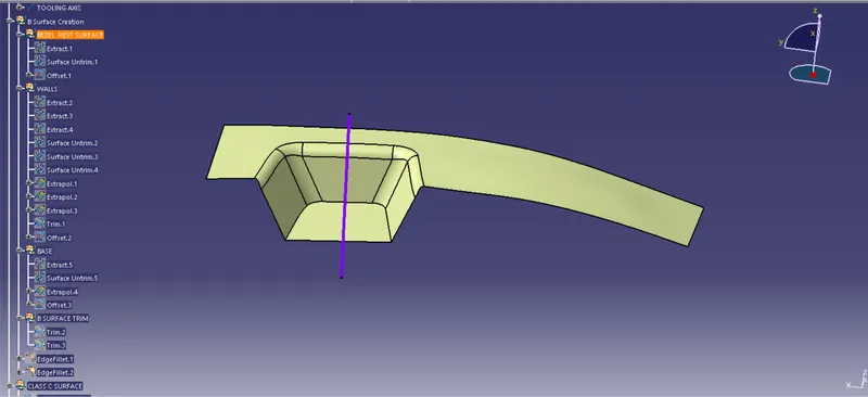
STEP 3- CREATION OF CLASS C SURFACE
- The C surface, an intermediary surface between A and B that is employed to give the design a closed surface appearance, is the next phase.
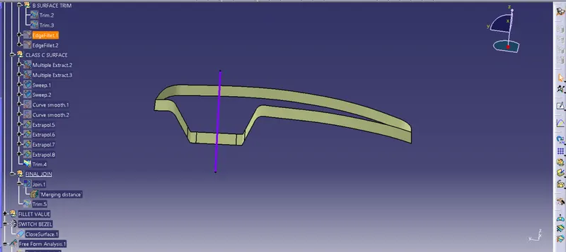
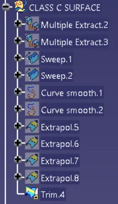
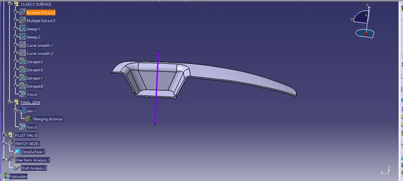
- The Guide curve with a subtype along the DRAFT direction is used as the boundary line of Class A, and the profile is used to sweep the C Surface.
- The tooling direction established earlier determines the sweep's direction.
A 3-degree draught angle is given for the sweep operation, and the surface is swept for a length above the designated part's thickness. - The complexity and spots along the swept surface are removed from the C surface utilizing the smooth Curve choices.
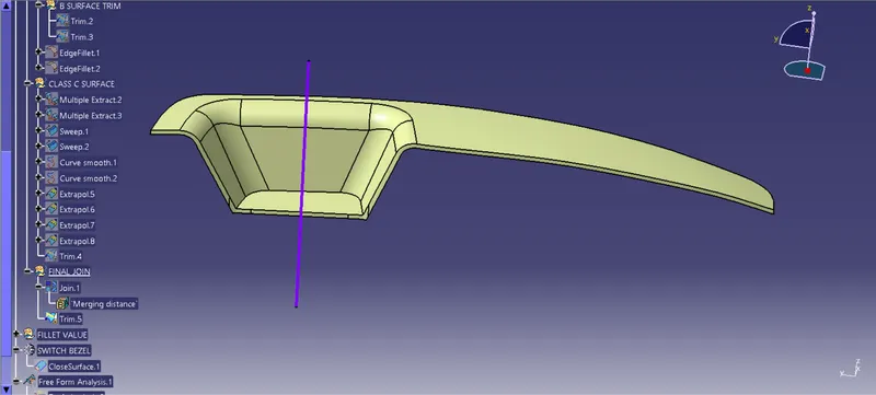
- In the end, the Class A and Class C surfaces are merged, and the connexity of the surfaces should be less than 0.003mm
STEP 4- FINAL TRIM AND JOINING
Final Product
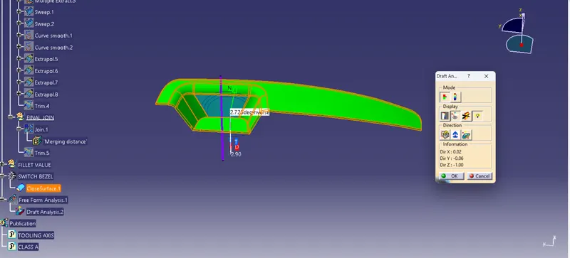
STEP 5 - DRAFT ANALYSIS
- The produced part needs to have its display frame's material mode updated.
- The axis system is then panned along the direction of the part and positioned parallel to the tooling direction by enabling compass definition.
- Applying Lock Direction fixes the compass, and then snapping at any position on the component creates the mode dialogue box.
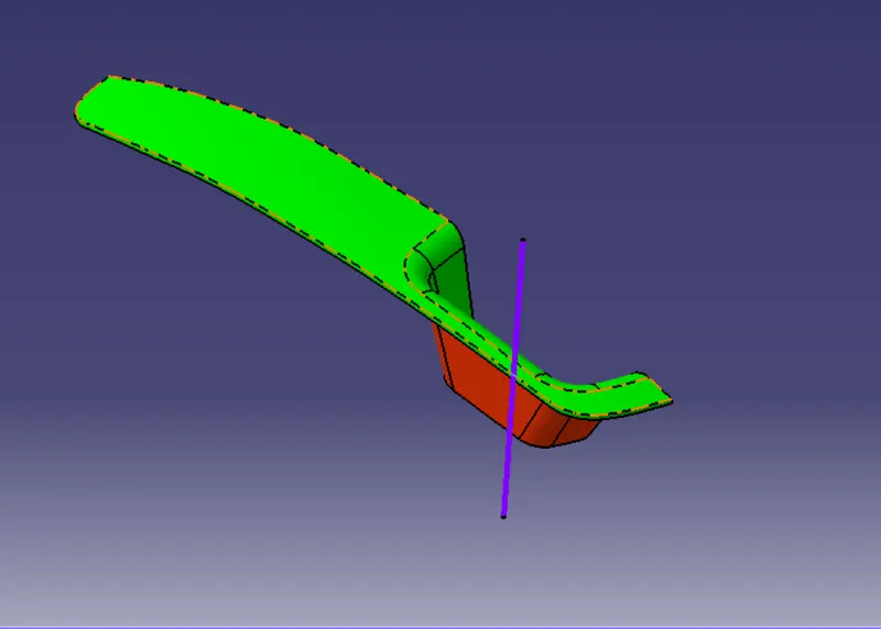
- Classification of the Color Codes and application of the Draft Angle.
- The study is then saved after using the Running point analysis to hover about the part and examine the permitted draft angles.
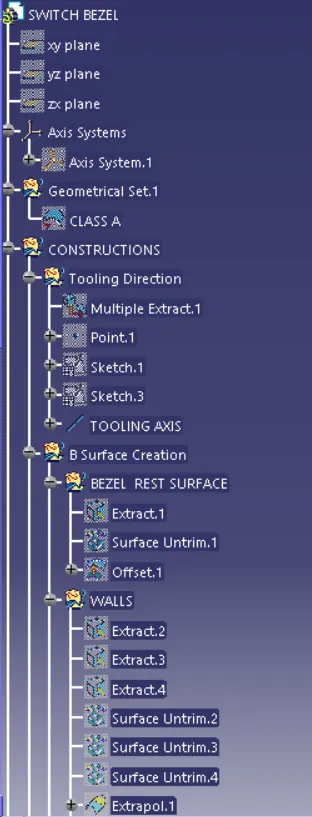
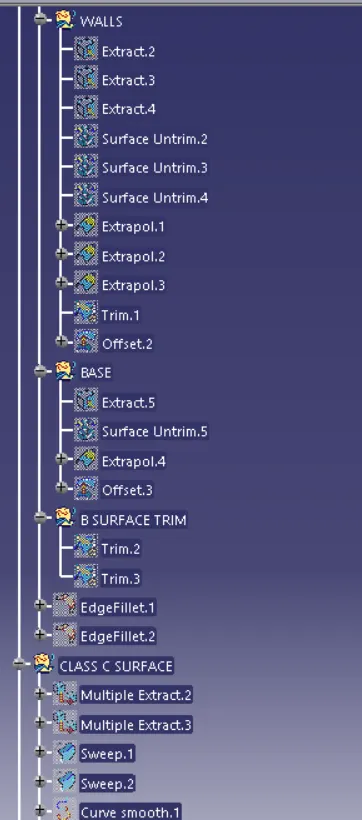
DESIGN TREE
ISOMETRIC VIEW
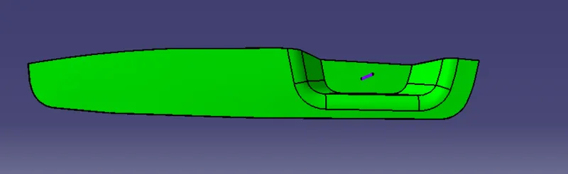
TOP VIEW
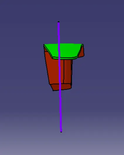
SIDE VIEW
FRONT VIEW