Week 8 - Challenge 2 - Switch Bezel Design
SWITCH BEZEL
AIM:
To Create the Switch Bezel Plastic component through the given Class-A surface by taking the Thickness of the component to be 2.5 mm. To begin with, the tooling axis for the given Class-A Surface should be created meeting the requirements of the draft angle and at the end perform the Draft analysis on the model.
OBJECTIVES:
- Checking continuity of class A surface.
- Deciding feasible tooling direction & creating tooling axis.
- Performing draft analysis on class A surface.
- Creating class B surface from given class A surface.
- Creating class C surface to join A & B class surface.
- Creating solid feature by using closed surface.
- Performing draft analysis on final plastic component.
PROCEDURE:
We will be recieving a styling class A surface from styling team who deveopes it from a concept sketch to aesthatic class A with styling software for eg:ALIAS.here our work is to get the class A and import it to the design tool to develop Class B & C surfaces.
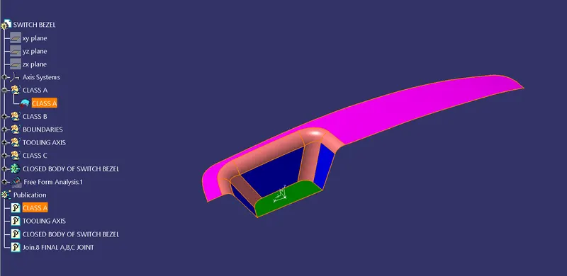
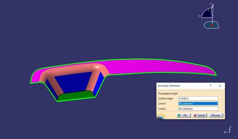
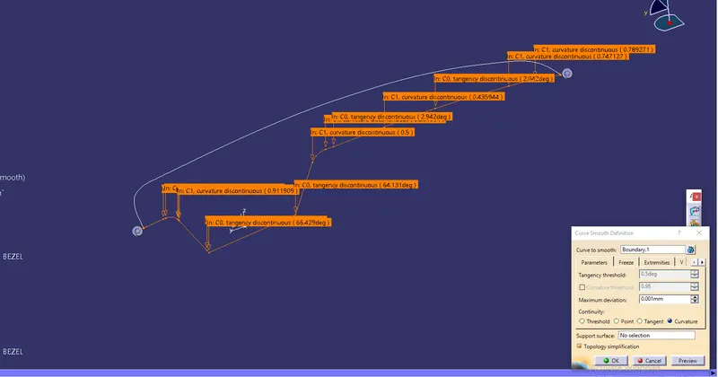
First of all we have to check continuity of given class A surface to ensure class A surface is properly joined or no discontinuity present. This can be done by using join or boundary command in CATIA . By looking visually in below image we see that surface has continuous connected boundary as highlighted by green line.
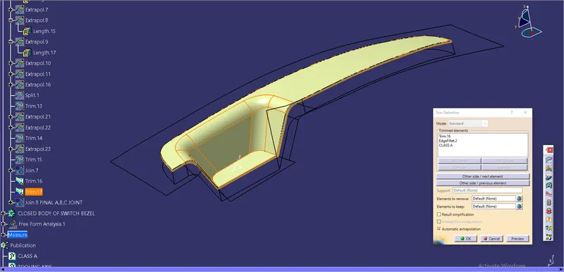
After checking the connectivity we will get into surface workbench to create a solid part having 2.5mm thickness from the given A surface, i.e the B and C surface had to be constructed. The B surface was constructed by extracting all the flat faces on the A surface. Once all the faces were extracted, untrimmed, extrapolated, and were trimmed to give a surface similar to that of the A surface. The surface was then offset by 2.5 mm in the direction where B surface was needed.
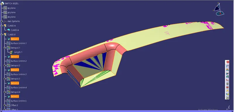
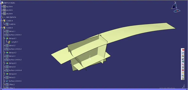
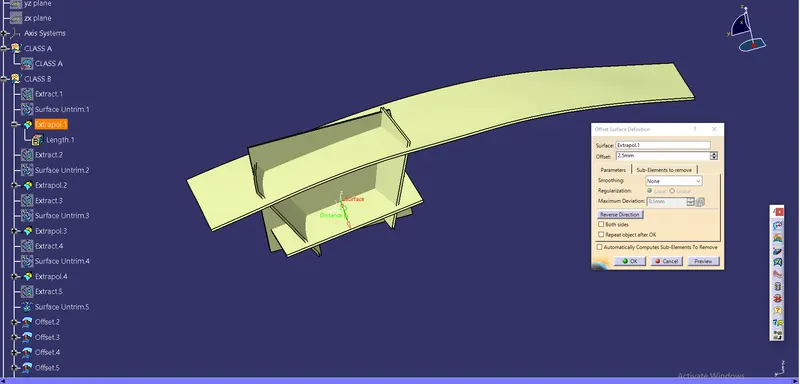
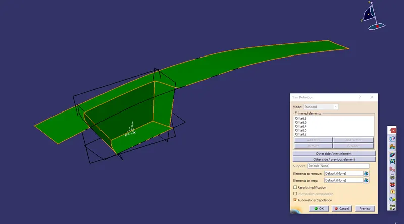
The next step was to add fillets to the B surface. In order to this, the fillets on the A surface were extracted and untrimmed and were measured using the Measure Item tool. Once the fillet values were known, it was possible to add them to the B surface.
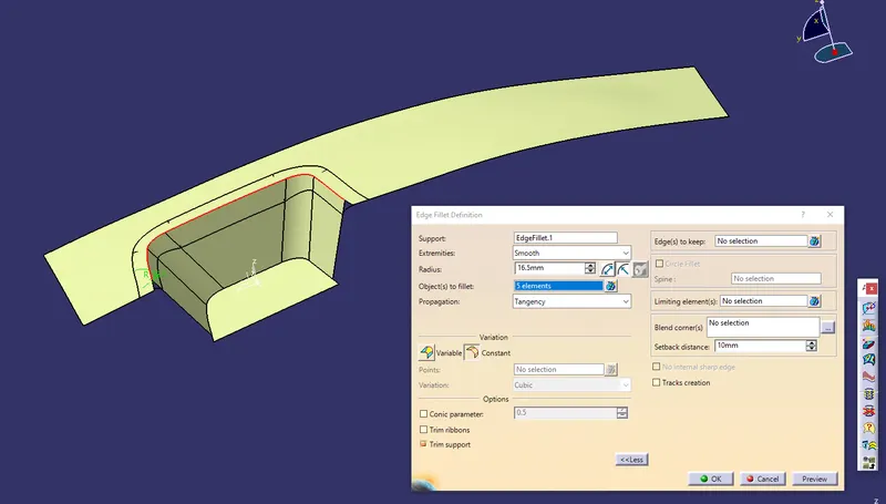
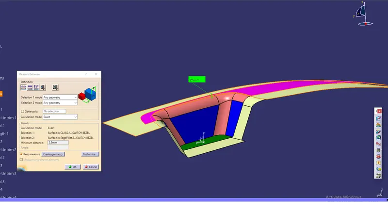
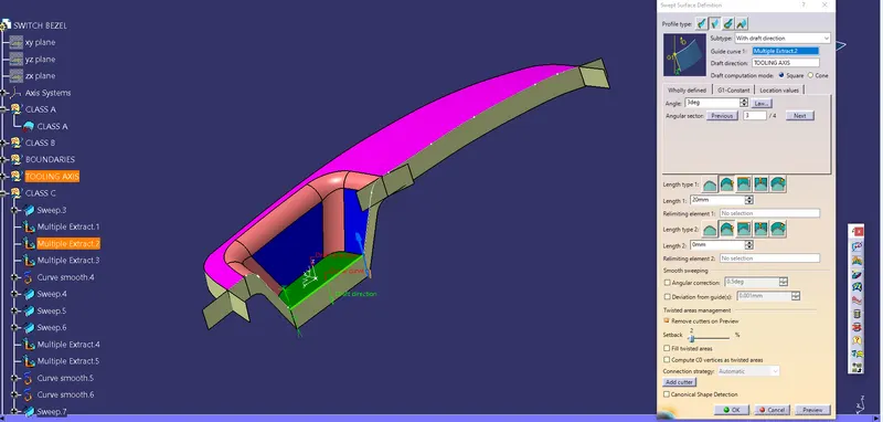
In order to construct the C surface, a boundary was created using the Boundary tool and the A surface was used as a reference. A surface was created using the Sweep tool-draft option, and the tooling axis was selected as the draft direction and a draft angle of 3 degrees was given. The A surface was extrapolated by 2 mm using point propagation and all three surfaces were trimmed in order to obtain the final part body.

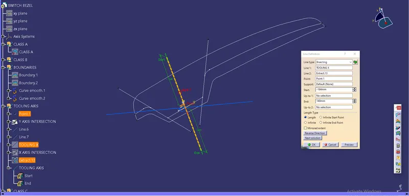
Now we will be creating a tooling axis for the given surface model. The tooling axis helps determine the direction along which the mould will open. First, a point was created on the center of the surface(highlighted in green) and the two opposite surfaces(highlighted in blue) were used as a reference and a line was created which bisected the two surfaces. This line was again bisected using the third face and a tooling axis was created.
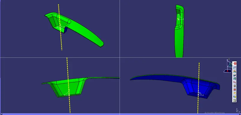
Now,draft analysis was carried out on the final body by inserting a Feature draft analysis. It was important that the part body was in customize view with material mode on. The first step was to turn on the compass option and to drag the compass and place it on the tooling direction in the correct orientation. Once it was placed, it has to be locked in that position. Then an 'x' cursor appears as we hover over the body and by clicking on it, the draft analysis is shown. The color code was red - negative, blue 0-3 degrees, and green above 3 degrees. Three degrees were chosen since it is the ideal draft angle for plastic components. The body was green which meant that it was a good design and that it would not cause any problems when the part is being extracted from the mould.
Below i have attached the Screenshots of the Draft analysis report for the final plastic component
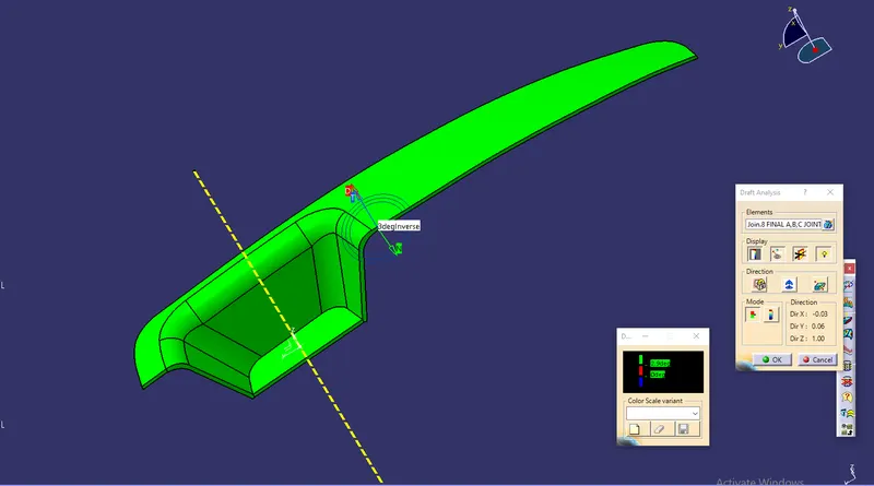
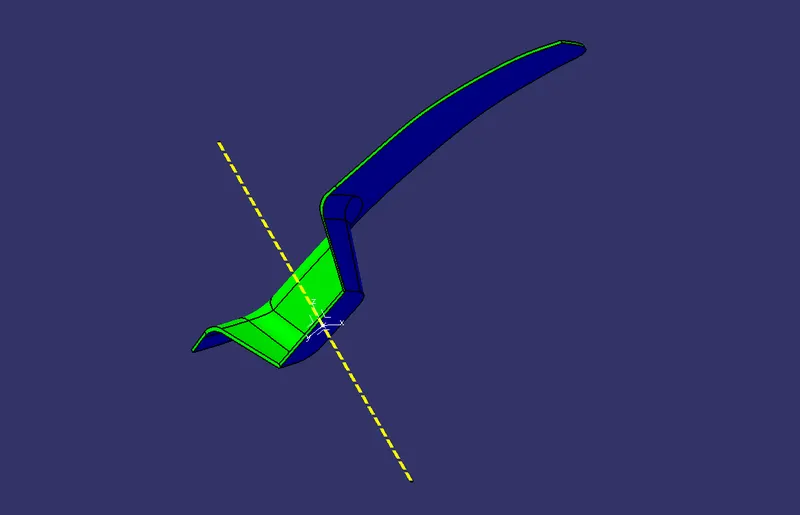
Screenshots of the solid model with the proper color code of the draft angle in various orientations (Isometric, Front, Side, and Top View)
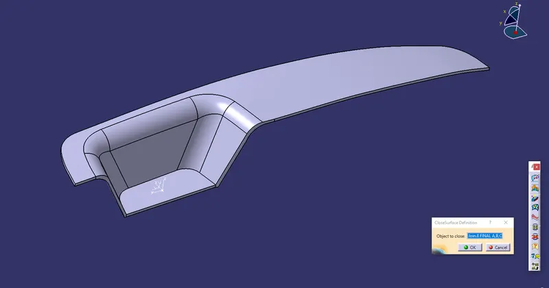
here i have Used the Close Surface feature to make a solid body from the surface.
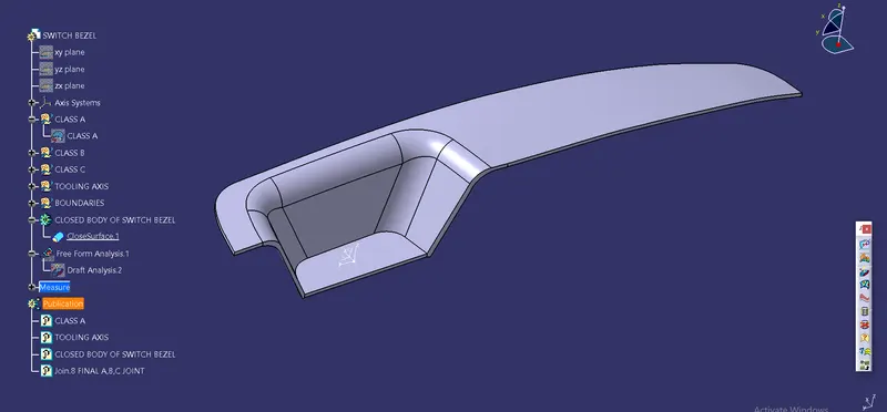
Note : before submission of model i make sure that i have included all the things are listed below
Ensure Proper Tree StructureGeometrical sets should have a proper name based on the sketches present inside of itAll the sketches should be created under the Geometrical setUse the Close Surface feature to make a solid body from the surface.Publications: Use the publication option and publish the belowTooling AxisClass A, B, and C surface
Screenshots of the Draft analysis report for both the given Class-A surface and the final plastic componentScreenshots of the solid model with the proper color code of the draft angle in various orientations (Isometric, Front, Side, and Top View)Submission as attachmentCATpart should be submitted as an attachment using the below Browse option.
RESULT:
By the end i have Created the Switch Bezel Plastic component through the given class-A surface by following the operations that are listed below :
- Checking continuity of class A surface.
- Deciding feasible tooling direction & creating tooling axis.
- Performing draft analysis on class A surface.
- Creating class B surface from given class A surface.
- Creating class C surface to join A & B class surface.
- Creating solid feature by using closed surface.
- Performing draft analysis on final plastic component.