Week 8 - Challenge 2 - Switch Bezel Design
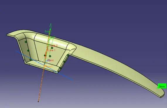
STEP 1) CREATING OF TOOLING AXIS
- A Reference Point is created along the Surface zero and new Axis system is created
- The X Direction along the Class A and Y direction along the Class A were used to create Tooling direction
- Finally the Tooling axis is created by bisecting the two lines and it is published. Class A Surface as input using surface operation commands Class B is developed
- The tooling Axis determines the direction of Class C boundary swept with draft direction.
- When viewing from tooling direction normal all the parts that are drafted should be visible so it gives an rough idea to determine product manufacturing in Injection molding.
STEP 2) CREATION OF CLASS B SURFACE..
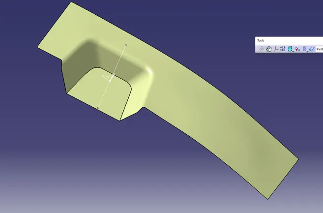
- The next step is to design B surface for the input which is usually the surface where all engineering aspects and support creations are done.
- The B surface Creation is performed using surface operations in CATIA which is an offset from Class A with dimension proportional to the thickness of the part
- In Switch bezel the B surface is offset 2.5mm from the input which is the thickness of the part
- The B surface is an extrapolated surface compared to A surface and forms the bottom skin of the part.
STEP 3) CREATION OF CLASS C SURFACE
- The Next step is to from the C surface which is an intermediate surface between A and B and is used to give the closed surface appearance to the design
- The C Surface is swept using the profile as boundary line of Class A which is the Guide curve with a subtype along draft direction.
- The Direction of the sweep is the tooling direction formed earlier
- The draft angle for the sweep operation is provided which is 3 Degree and surface is swept for length above the thickness of the specified part
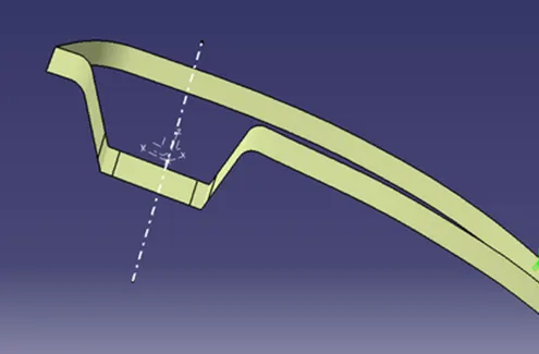
- The C surface is refined using smooth Curve options to remove the complexity and patches along the swept surface
- Finally the Class A and Class C surfaces are joined together and connexity of surfaces should be less than 0.003mm and the surfaces are merged.
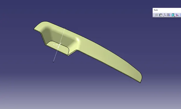
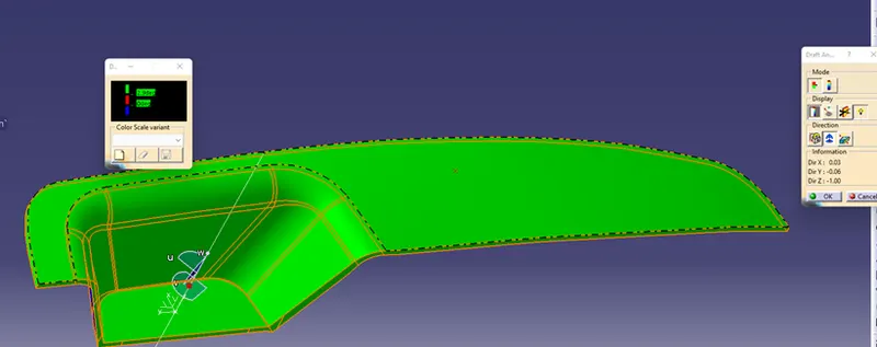
STEP 4) DRAFT ANAYLYIS
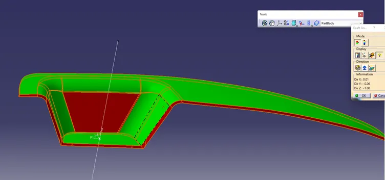
- after checking we found below 3 degree surface
- so after remodified tooling axis 3 degree to 5 degreee the results are shown below..