Roof challenge
CAR BIW ROOF
- An automobile roof or car top is the portion of an automobile that sits above the passenger compartment, protecting the vehicle occupants from sun, wind, rain, and other external elements. Because the earliest automobiles were designed in an era of horse-drawn carriages, early automobile roofs used similar materials and
- The use of aluminium for the car roof is well established in all-aluminium car body designs. But there are also significant aluminium applications in the roof of vehicles with steel car body
- Weight reduction in the roof (i.e. lowering the centre of gravity) has always been a high priority topic in automotive design. However, the roof is generally an integral part of the body-in-white. Therefore, the integration of structural aluminium components into the roof of a steel body structure requires an in-depth consideration of different
Design Requirements for the roof and its components
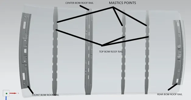
- FRONT BOW ROOF RAIL
- CENTER BOW ROOF RAIL
- SUPPORTING BOW ROOF RAIL
- REAR BOW ROOF RAIL
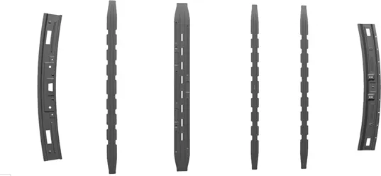
FRONT BOW ROOF RAIL
This is master section of the bow roof rail.
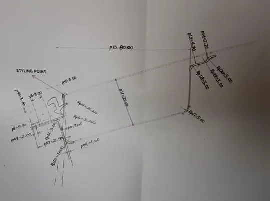
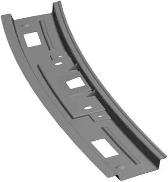
Front bow roof rail provides strength to the roof panel from front and its act as link between windshield glass, roof panel and headliner.
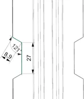
Ditch area.
Ditch area the tool opening angle is only 3 degrees.
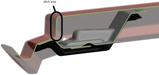
Emboss is provided to give strength for a front roof panel
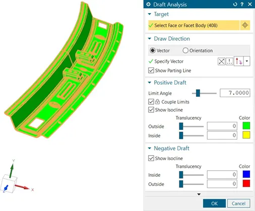
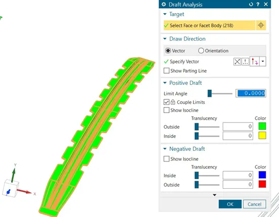
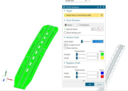
Here opening angle taken is 7 deg because the model will not pass the draft analysis as for sheet metal the draft angel is 7 deg
REAR BOW ROOF RAIL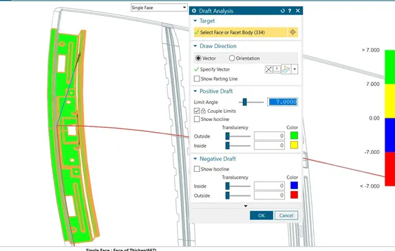
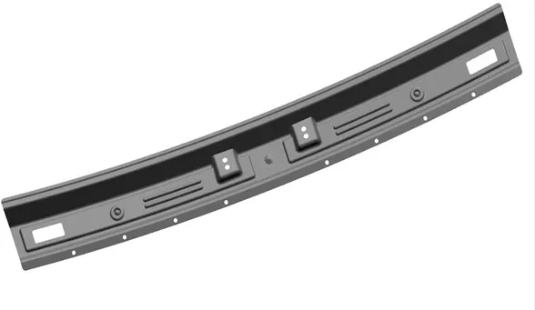
The master section of the rear bow roof rail
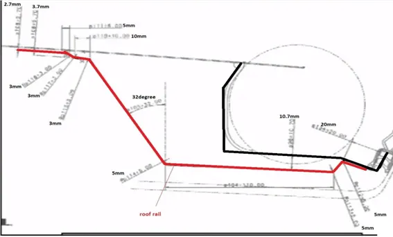
Section view of rear bow roof
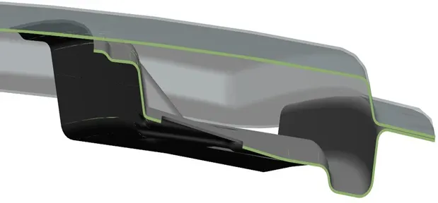
Final part of rear bow roof rail
Draft analysis
SUPPORTING BOW ROOF RAIL
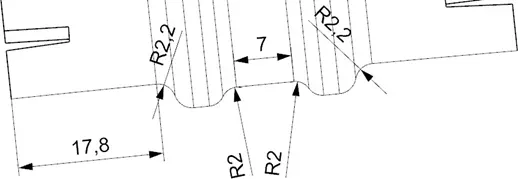
SECTION VIEW OF SUPPORTING BOW ROOF
Supporting bows are supporting the roof panel which stress generate by some luggage and equipment.
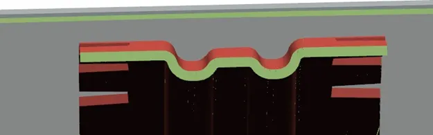
MASTIC POINTS
It used to fix the supporting bow roofs as well as spot welding used to fix Cutting dimension in sheet metal as shown below same for all supporting bows.
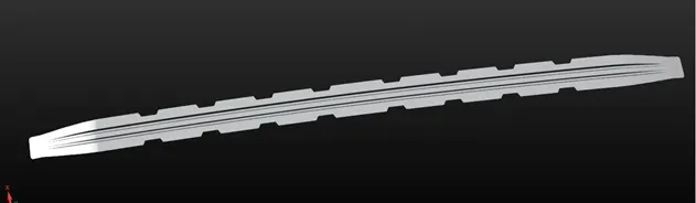
Final part of bow roof
Draft anaylsis
It used to determine the design is manufacturable or not
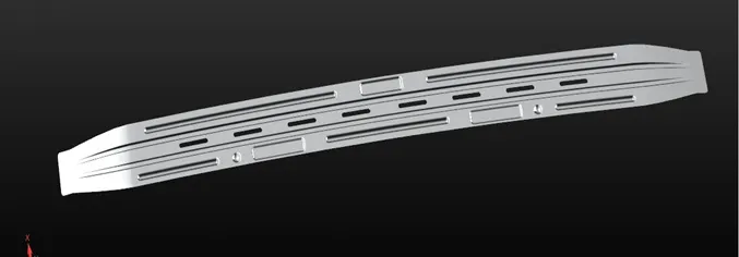
CENTER BOW ROOF
Center bow roof should provide maximum strength to reduce stress
Draft analysis
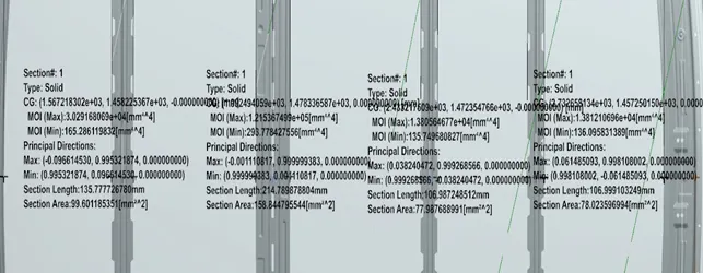
Section modulus of all 4 supporting bow roofs
- Heat distortion area
It is temperature limit above which material be used for structural application.where the material start to soften when exposed to a fixed load at elevated temperature. In order to avoid bending/damages on roof, based on heat distortion temperature,this study will determine the strength of roof
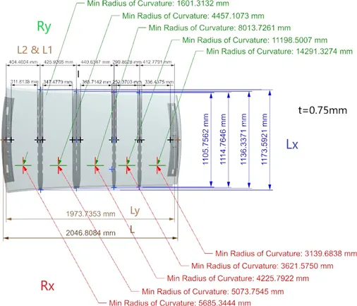
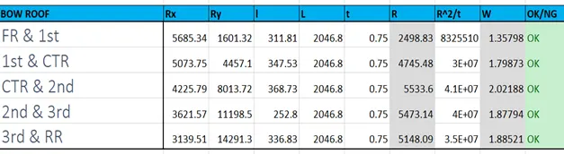
Calculated dimension in design is given below
Formula is -
W = [1.73 x 10^(-3) x L] + [1.85 x 10^(-8) x (R^2)/t] + [ 1.10x10^(-3) x l] - 2.68
Judgement Condition : OK< 2.7> 3.1 Where
L = Roof Length in X-Direction[mm](Roof dimension in 0-Y) R = Roof curvature
R = 2(Rx*Ry)/(Rx+Ry) Rx = X curvature
Ry = Y curvature
t = Roof plate thickness [mm] l = Bow Roof Span [mm]
B. Snow load criteria
This evalution is performed in cold region where snow occurs. Roof design must pass through these calculations to ensure that it has sufficient stiffness to withstand the load to snow over the roof
Qr = [Iy x t2] / [α x s x [(Rx + Ry)/2]2 x 10-8]
Where
α = My x Lx2 x 10-12 , My = Y(Ly-Y)
Judgement condition = Qr ≥ 3.1
250 ≤ s ≤ 380
t = Roof plate thickness [mm]
Ly = Distance between the front and rear roof Rails on the Vehicle along with 0Y[mm]
Length of Roof panel with the center point between Roof rail Front /Rear as the reference point of the front and the rear.
Lx = Distance between the Left and Right end of the roof on the Roof BOW [mm] Width of the roof panel exposed on the surface.
Y = Distance front Front Roof Rail to Roof BOW[mm]
s = Distance for which Roof BOW bears divided load [mm] s = L1/2 + L2/2
Iy = Geometrical moment of inertia of Roof BOW (Y cross-section )[mm4]
Rx = Lateral direction curvature radius of roof panel Y cross-section on Roof BOW [mm] Roof panel curvature Radius of the Length Lx in Front view
Ry = Longitudinal Direction curvature radius of the Roof panel X cross-section on Roof BOW [mm]
Roof panel X curvature radius of length s in Side view
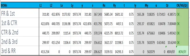
Note- By incearsing the thickeness of the all supporting bows the moment of inertia increases with increasing snow load
(Increased thickness of supporting bow roofs 0.75 -1.5mm)
Conclusion
We studied that design of front bow roof rail, rear bow roof rail and center bow roof rail by checking draft analysis. using solid model design we calculated the modulus of inertia using nx cad software