Week 8 - Challenge 2 - Switch Bezel Design
Title: Switch Bezel Design Using CATIA V5
Objective:
To create the Switch Bezel Plastic component through the given Class-A surface. As well as, creating the tooling axis for the given Class-A Surface which is meeting the requirements of the draft angle and at the end perform the Draft analysis on the model.
CLASS A SURFACE :
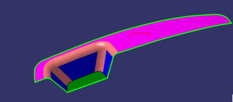
Tooling Direction :
Tooling axis is the direction in which mold or core and cavity opens. The ejection of the part from mold depends on the draft. A zero draft can result in difficult or no ejection due to shrinkage. It is recommended to add a minimum of 0.5 to 1 degree of the draft for non-textured surface & 3 to 5 degree of draft for textured surfaces.
Procedure to create the tooling axis using bisecting method :
1. First, ensure that the Class-A surface is properly joined and has no discontinuity. Select the boundary command from the toolbars and then select the Class-A surface. A boundary should only appear on the outer edges of the component. Then, we decide the proper tooling axis direction with respect to the given component (in this case it is the Z-axis direction).
2. After that, we create a point and an axis system on the Class-A surface and then create two sketches on the zy and zx planes respectively.
3. Firstly we will create a point on the base surface (YZ plane) for the intersection lines.
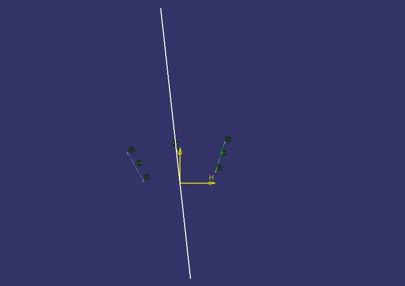
4. In the first sketch on the zy plane, we will draw two inclined lines coinciding with the intersection curve of the Class-A surface along the y-axis direction. Then we will create a bisecting line with these two lines.
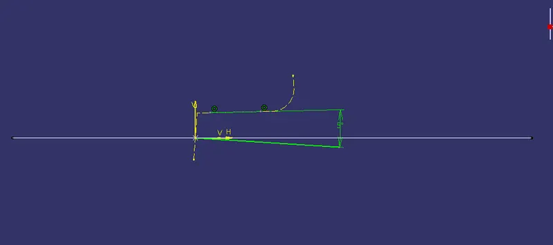
4. For the sketch on the zx plane, the same procedure is done but on one side we don’t have inclined lines so the center point is used to extrude a line along the z-direction and gave a measurement of 5 degree.
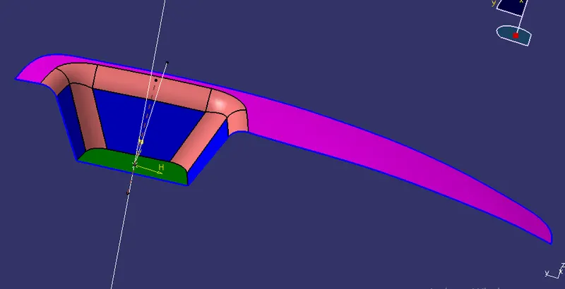
5. we create the tooling axis by creating a bisecting line with the two previous lines on the point that we created on the Class-A surface.
CLASS B SURFACE :
- We will create extraction of the all sides for the class B surface
- After extraction we will untrim then extrapolate the extract parts. Note that all the parts are intersecting
- After this we will trim the surfaces and we will get our B surface.
- As per the requirement we have taken the thickness of 2.5 mm everywhere.
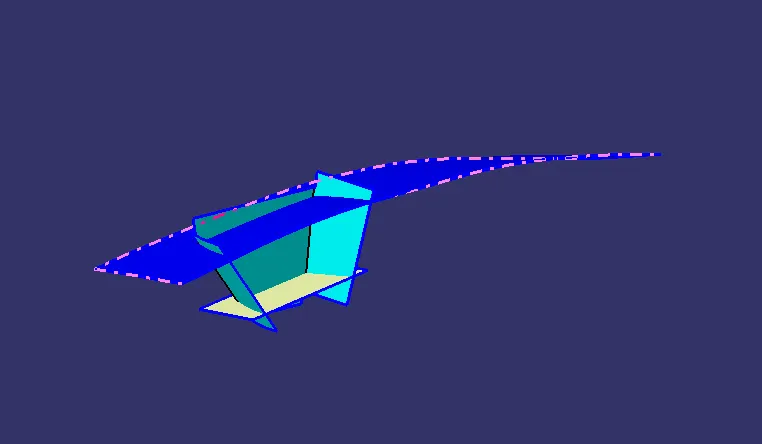
Here we have our final class B surface with given fillets.
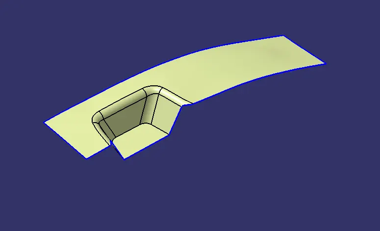
CLASS C SURFACE :
For class C surface, we have to extract all the boundary and sweep them all.
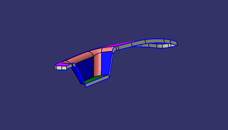
After adding class A surface to class C surface.
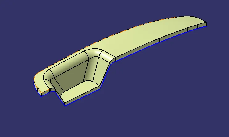
After trimming the final class C surface with class B surface. we will get our final product, check with boundary wheather it is open or not.
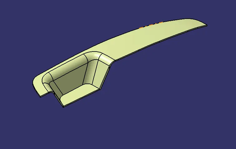
VIEWS :
After thickning the final product with close surface.
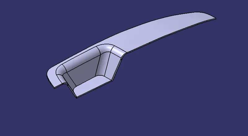
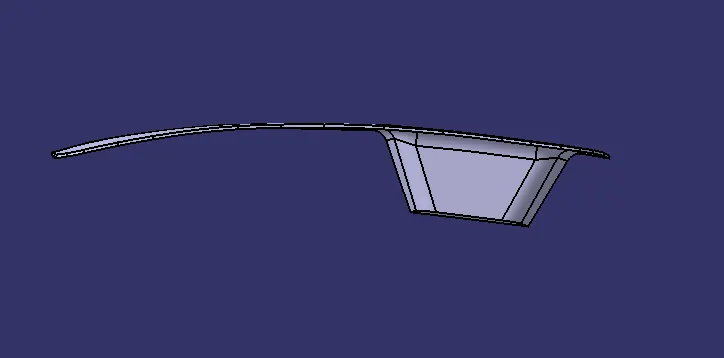
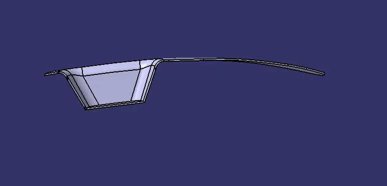
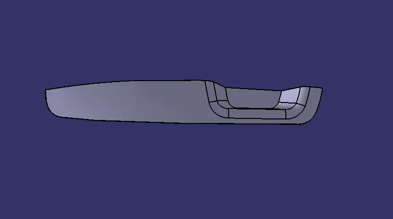
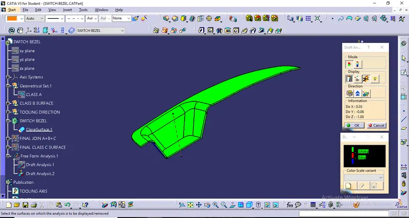
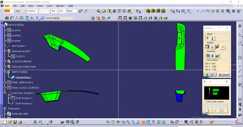
DRAFT ANALYSIS :
For draft analysis on the solid body, I have took the maximum draft angle of 2.8 degree and minimum of 0 degree.
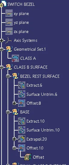
TREE STRUCTURE :
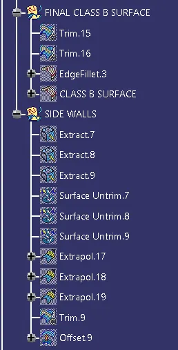
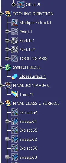
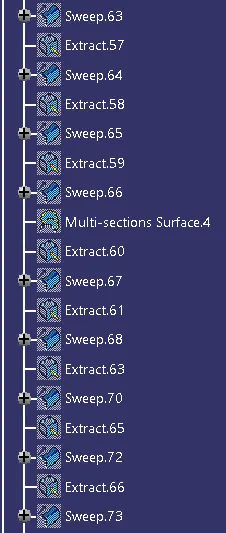
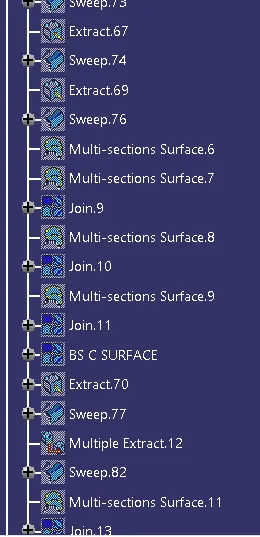
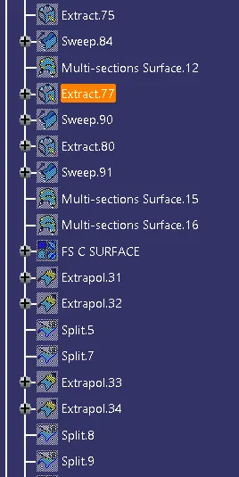
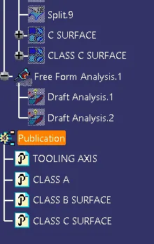
DRAFT ANALYSIS :
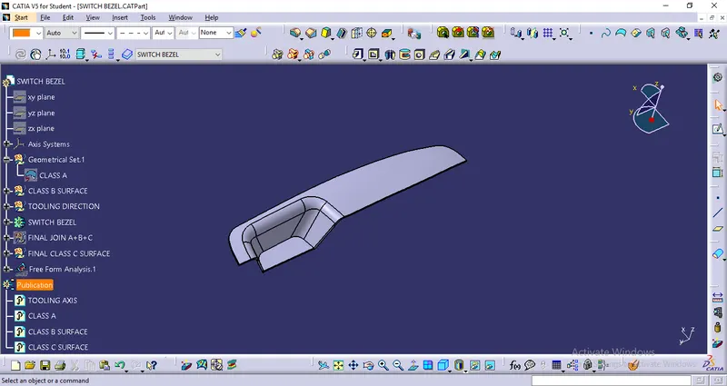
CONCLUSION:
Finally, We Created the Switch Bezel Plastic component through the given Class-A surface with, the tooling axis and we performed the Draft analysis on the model.