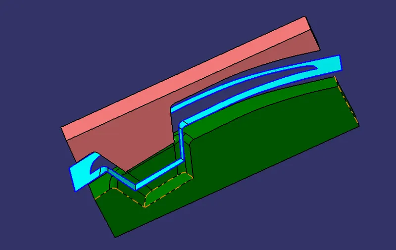
Week 8 - Challenge 6 - Core & Cavity Design
AIM : To Create the Core and cavity blocks for the switch bezel designed in the earlier challenge.
CLASS A SURFACE:
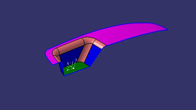
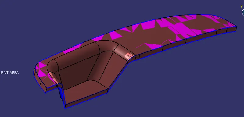
DRAFT ANALYSIS :
The Draft Analysis command enables you to detect if the part you drafted will be easily removed. This type of analysis is performed based on color ranges identifying zones on the analyzed element where the deviation from the draft direction at any point, corresponds to specified values.
For draft analysis on the solid body, I have took the maximum draft angle of 2.8 degree and minimum of 0 degree.
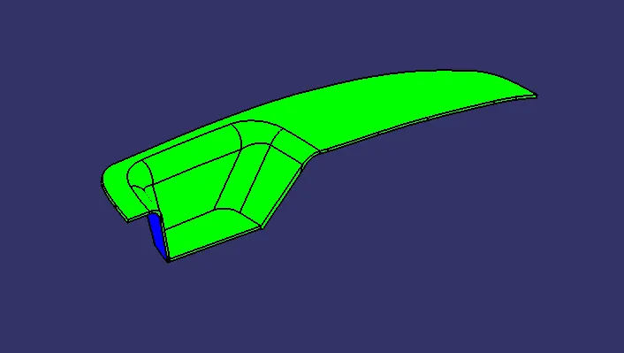
TOOLING AXIS :
- Firstly we will create a point on the base surface (YZ plane) for the intersection lines.
- In the first sketch on the zy plane, we will draw two inclined lines coinciding with the intersection curve of the Class-A surface along the y-axis direction. Then we will create a bisecting line with these two lines.
- For the sketch on the zx plane, the same procedure is done but on one side we don’t have inclined lines so the center point is used to extrude a line along the z-direction and gave a measurement of 5 degree.
- we create the tooling axis by creating a bisecting line with the two previous lines on the point that we created on the Class-A surface.
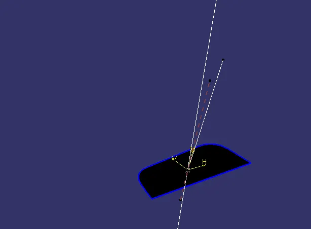
PARTING SURFACE :
- For parting surface we have to creat a boundary at class A surface
- Then extrapolate it according our requirement .
- Trim it with the class C and B surface, hence we get our final parting surface.
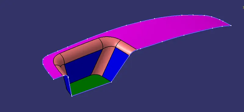
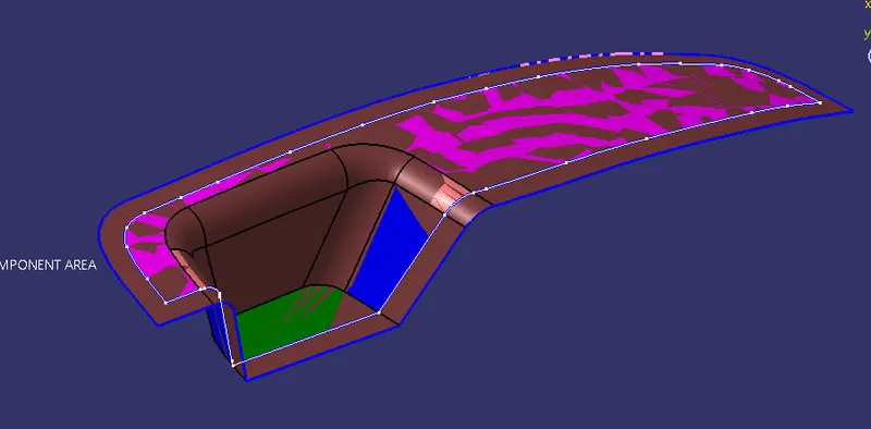
PARTING SURFACE WITH COMPONENT -
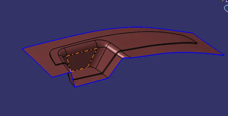
MAIN PARTING SURFACE-
The parting surface of a mould are those surfaces of both mould plates adjacent to the impressions which butt together to form a seal and prevent the loss of plastic material from the impression. The parting surfaces of a mould are those portion of both
mould plates, adjacent to the impressions, which butt together to form a seal and prevent the loss of plastic material from the impression.
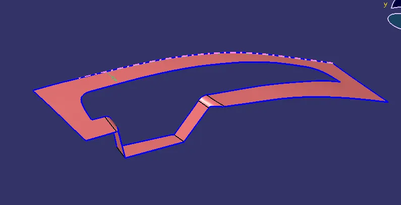
PARTING LINE:
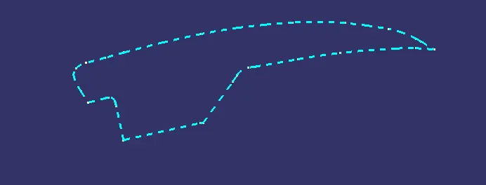
It is the area in which parting surface and component meets Or it is a junction between core and cavity and the parting surface has some set of rules because the product quality mostly depends on the parting surface.
CORE AND CAVITY-
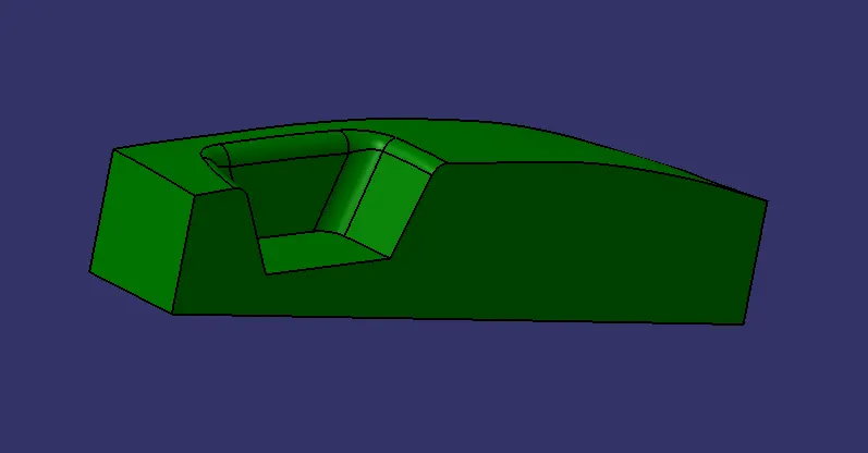
A core is the one part of the mould.and it is respponsible for half of the molded part. actually core is the projection of the bodyand cavity is the depression of the body. these core and cavity combines to form a mould. then the plastic material injected into these mould to get a plastic part.
CAVITY DESIGN :
- Firstly we have created a rectangulat plane on sketch workbench
- Extrude it according to requirement.
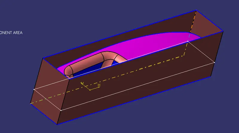
- Trim the extrude surface with the class A surface.
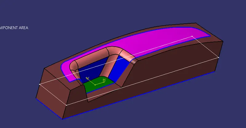
- Fill it with the boundary of trimmed surface bottom side.
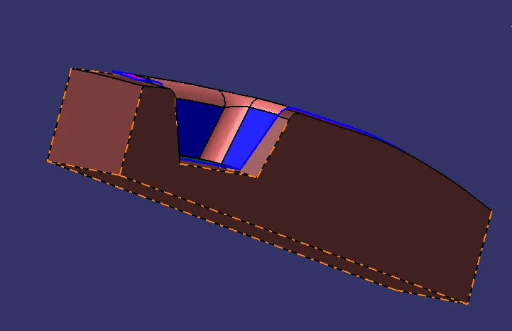
- Then thicken it with the close surface.
CORE DESIGNING :
- We have to same extrude for the cavity and trim it with the class A surface.
Hence we get our cavity.
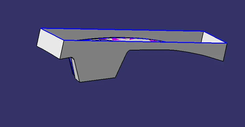
- Then we have closed our cavity with the same fill surface using boundary.
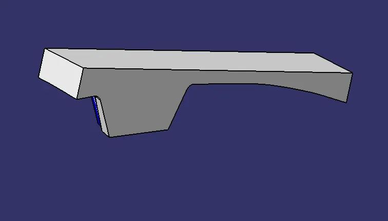
- Then solidify the cavity part using close surface.
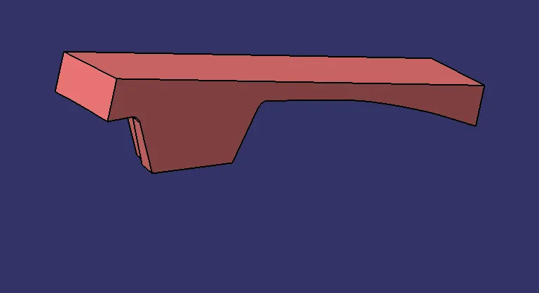
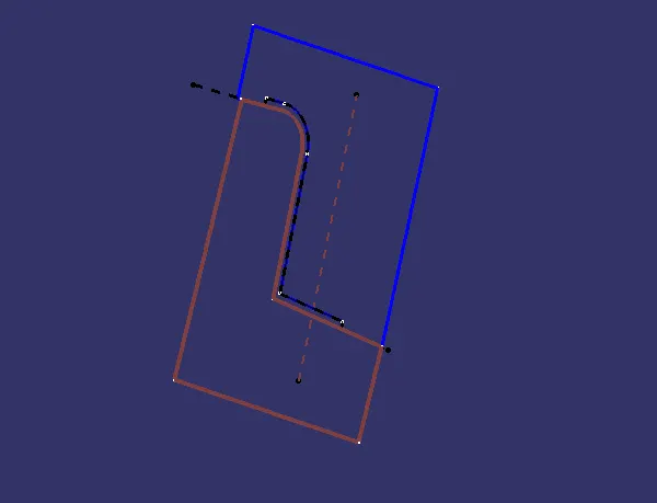
This is our final parting sketch with parting line, core line and cavity line.
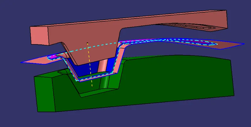
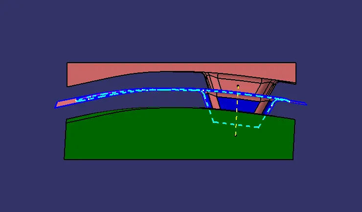
VIEWS:
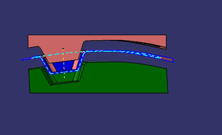
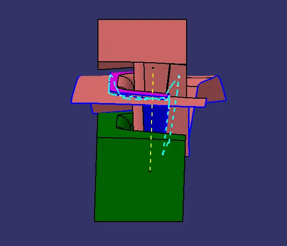
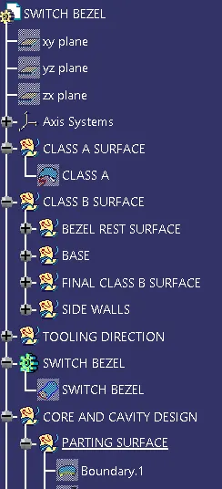
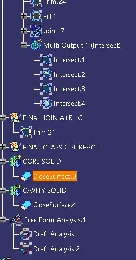
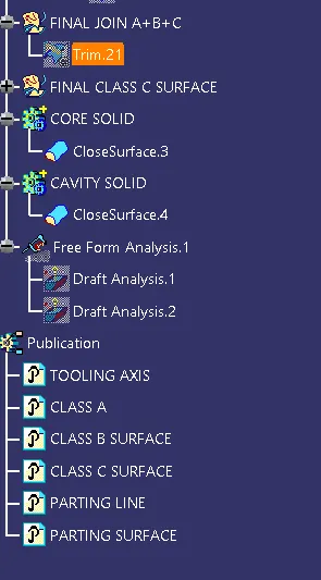
TREE STRUCTURE-
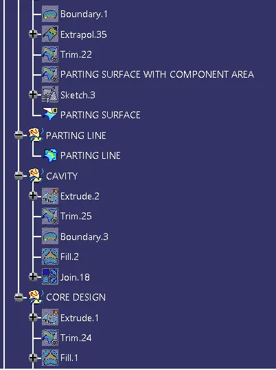
CONCLUSION: Finally we have Created the Core and cavity blocks for the switch bezel that we designed in the last challenge.