Week 8 - Challenge 1 - Base Bracket Design
Aim :- To design the Base Bracket plastic component through the given Class-A surface.
Objective : To create the Base Bracket Plastic component through the given Class-A surface. As well as, creating the tooling axis for the given Class-A Surface which is meeting the requirements of the draft angle and at the end perform the Draft analysis on the model.
Tooling Axis :
Tooling axis is the direction in which mold or core and cavity opens. The ejection of the part from mold depends on the draft. A zero draft can result in difficult or no ejection due to shrinkage. It is recommended to add a minimum of 0.5 to 1 degree of the draft for non-textured surface & 3 to 5 degree of draft for textured surfaces.
Procedure to create the tooling axis using bisecting method :
1. First, ensure that the Class-A surface is properly joined and has no discontinuity. Select the boundary command from the toolbars and then select the Class-A surface. A boundary should only appear on the outer edges of the component.
2. Then, we decide the proper tooling axis direction with respect to the given component (in this case it is the Z-axis direction).
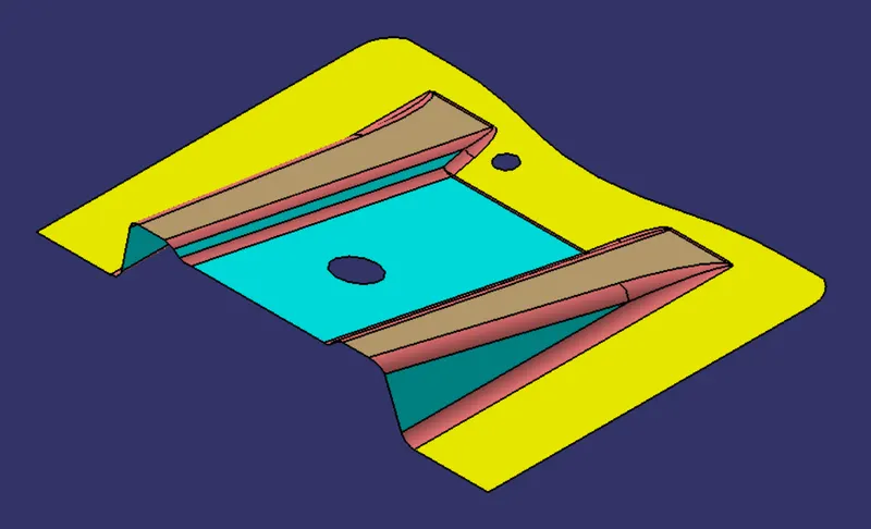
3. Create a point at the center of the hole ( where we have good commands in our surface )
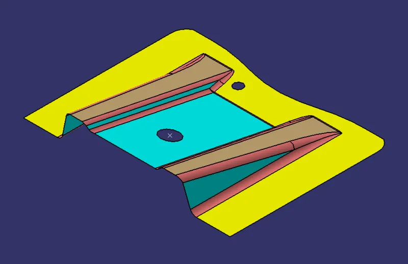
4. Then create an intersection by using the intersect command, taking the yz plane of the new axis system and the points as references.
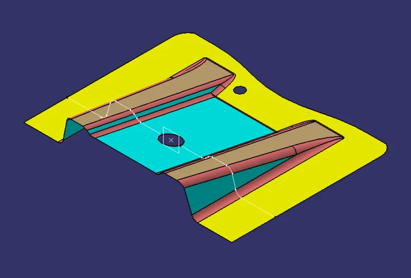
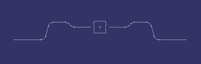
5. Then, we create two lines which are on the edges of the two side ribs of the Class-A surface.
6. we create the tooling axis by creating a bisecting line with the two previous lines on the point that we created on the Class-A surface.
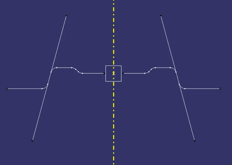
Class B surface:
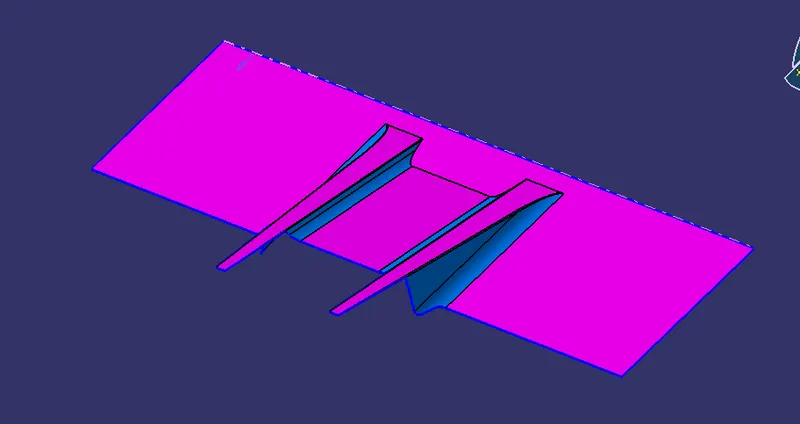
Class C surface :
C-Surface connects the class A-Surface and B-Surface. It is created using Sweep command. Boundry of the class A-Surface is swept along the tooling direction.
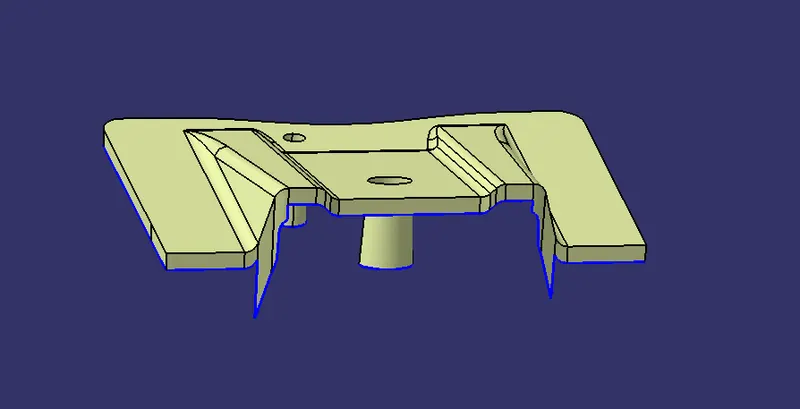
Trim Surface :
A & C-Surface are joined together then it is trimmed along the B-Surface.
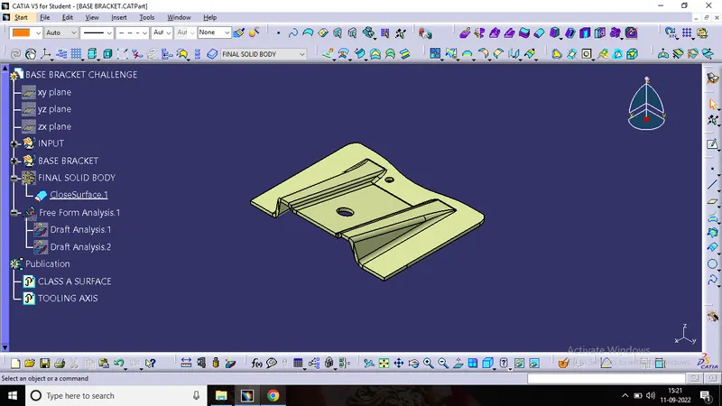
Solid body :
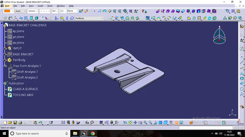
Draft analysis :
Draft analysis is performed based on color ranges identifying zones on the analyzed element where the deviation from the draft direction at any point, corresponds to specified values. Minimum draft angle is considered as 3 degree.
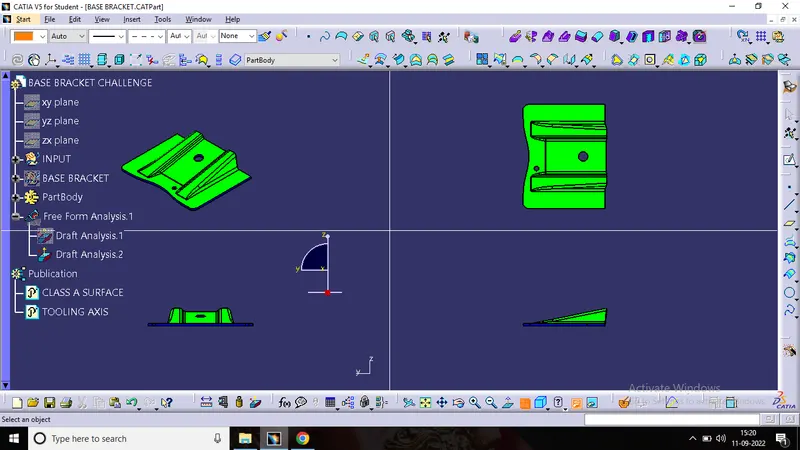
Tree Structure :
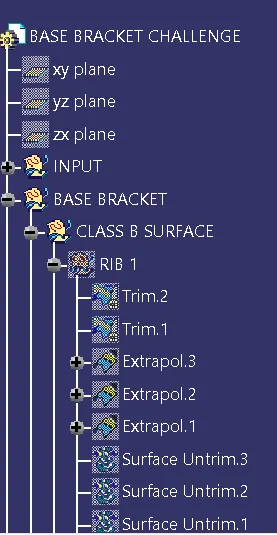
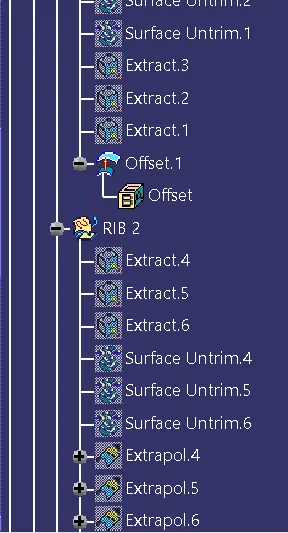
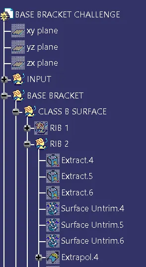
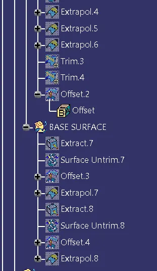
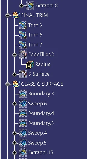
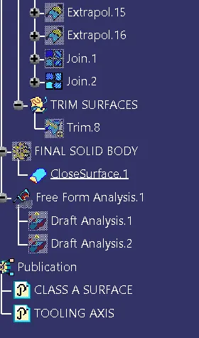
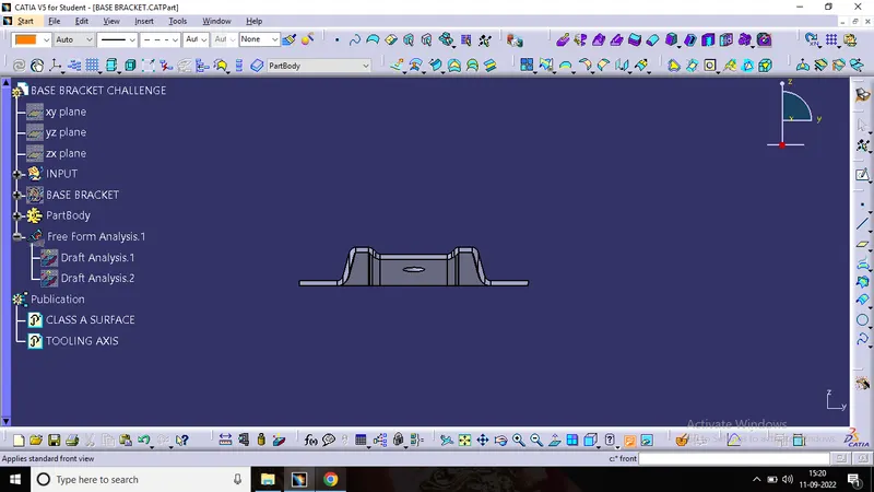
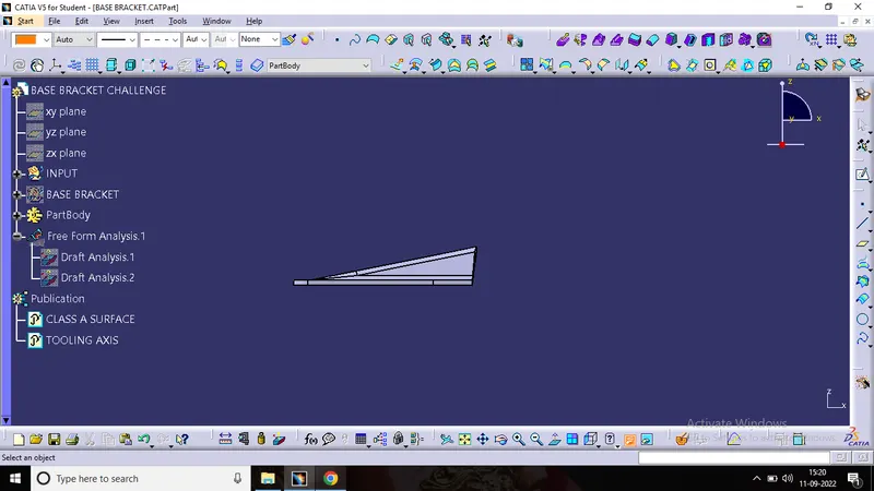
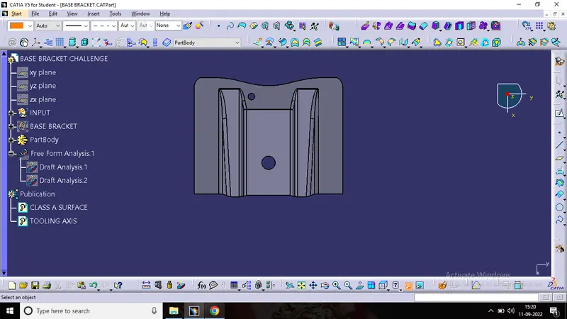
Views of Model :
Conclusion :
Thus the base bracket plastic component has been designed using the given class-A surface.