Week 8 - Challenge 2 - Switch Bezel Design
Create the Switch Bezel Plastic component through the given Class-A surface. To begin with, the tooling axis for the given Class-A Surface should be created meeting the requirements of the draft angle and at the end perform the Draft analysis on the model.
Take the Thickness of the component to be 2.5 mm
SOLUTION:
Screenshots of the Draft analysis report for both the given Class-A surface and the final plastic component
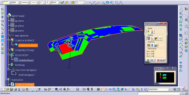
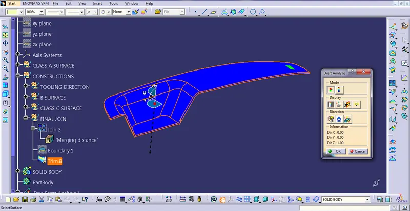
ISOMETRIC VIEW
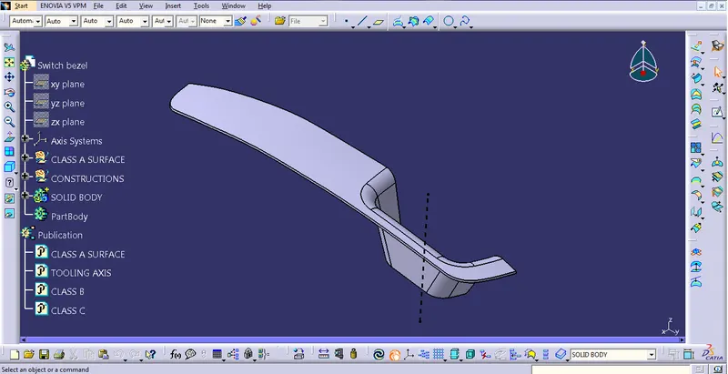
FRONT VIEW
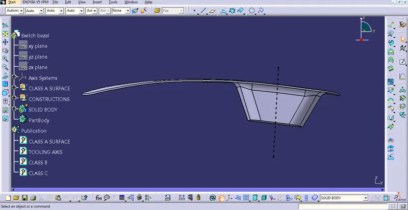
SIDE VIEW
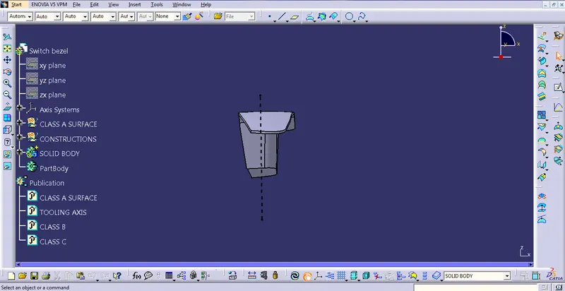
TOP VIEW
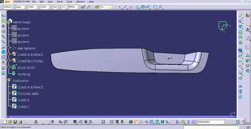
A detailed report should be done explaining the draft analysis
Draft Analysis is the process in which we can decide whether the class A surface is perfect for moulding or not. The standard draft required is a minimum of 3 degrees in the plastic industry. To check that, we have to create a tooling axis with the help of the given class A surface.
An explanation should be given on the way of creating the tooling axis, particularly the Bisecting method.
Here I have used bisecting line method to create the tooling axis. The first step is to create intersecting sketch with the help of intersect command. We get tilted lines in that sketch. With that help, we can draw lines on the same sketch and then extend it. Once we get angled lines, use a bisecting line from the line command to get the middle line from those two angled lines.
Do this same in another plane and we will get another bisecting line. In the end, we can get out the tooling axis by using both bisecting lines.
In another method, we have to create a centre point on a flat surface using the point command and then with the help of the line command, we will get out the final tooling axis.