Week 8 - Challenge 2 - Switch Bezel Design
SWITCH BEZEL DESIGN
Aim -
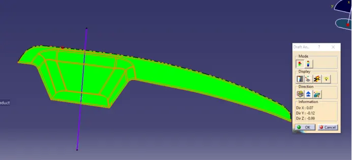
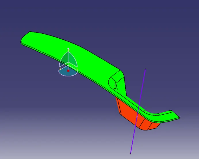
Create the Switch Bezel Plastic component through the given Class-A surface. To begin with, the tooling axis for the given Class-A Surface should be created meeting the requirements of the draft angle and at the end perform the Draft analysis on the model.
Method Followed -
- Creating a tool axis.
- Creating Class B surface from given Class A surface.
- Creating Class C surface from Class A & B surface.
- Creating a solid body by using a closed surface.
- Performing a draft analysis.
Creating tool axis -
- To create the tooling axis, we need the proper orientation or view that gives the correct features and draft available in the component.
- So here the component view from the Z direction gives the proper view for the tool to see the features present in the geometry.
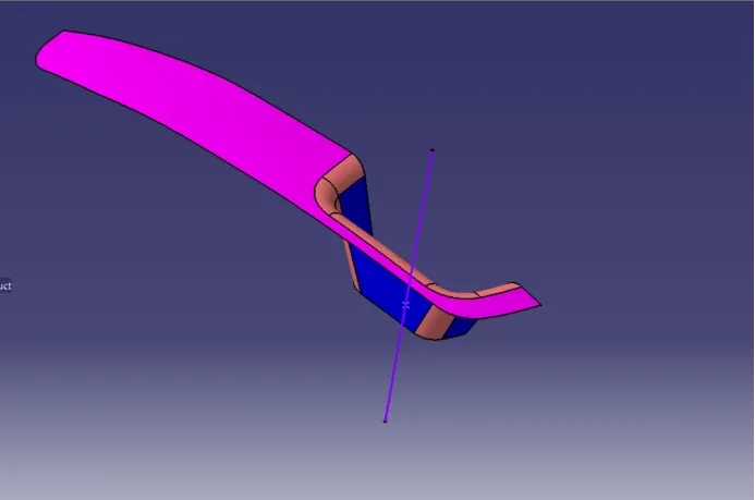
The tooling axis is created by the following steps -
Extracted the base surface.
The Center point is created by using a surface at zero.
At that point, an axis system is created.
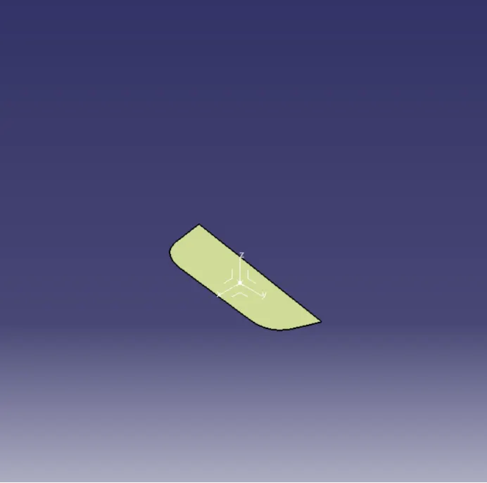
Take an intersection on the YZ plane to get a boundary line.
Made a dummy axis line to form a tooling axis by bisecting two lines.
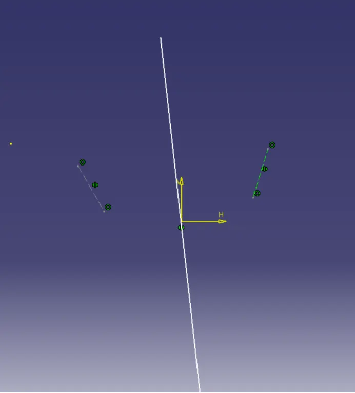
After that, I switched the surface and sketched on the XZ plane.
Using the axis center point, a line is drawn in sketch mode and it is constrained at the angle of 4 degrees.
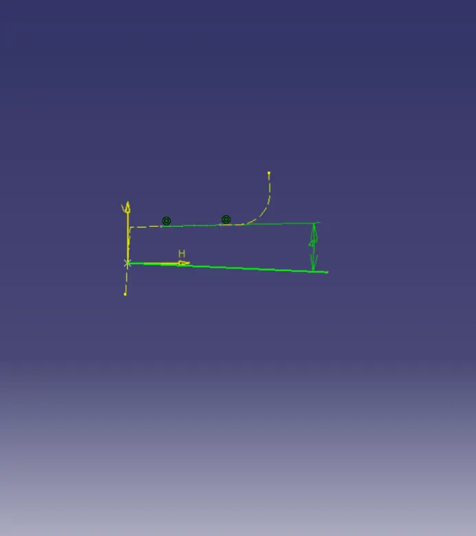
At last, both the lines are bisected to get the Final tooling axis.
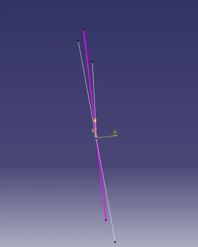
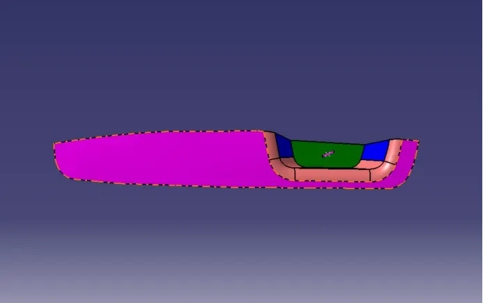
- We extracted a Class A surface and worked on it separately to create Class B surface
- Base
- Walls
- Bezel rest surface
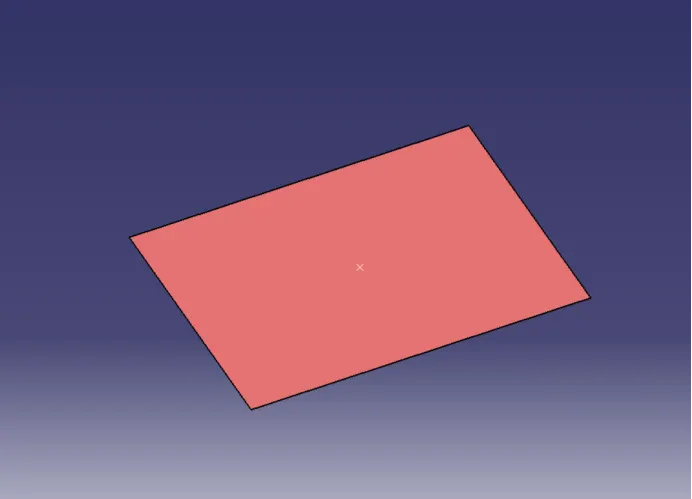
- Base -
- Extract the surface
- Untrim the surface
- Extrapolate it
- Offset it by 2.5mm to the downward.
- Walls -
- Extract the three walls separately
- Untrim the surface of three extracts
- Extrapolate them
- Trim them with each other.
- Offset the given surface by 2.5mm to the outward direction.
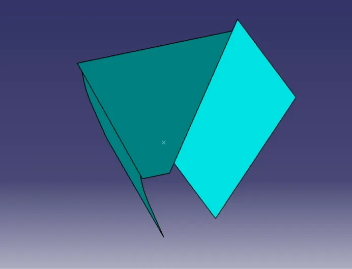
- Bezel rest surface -
- Extract it
- Untrim the surface
- Extrapolate it
- Offset by 2.5mm to the downwards.
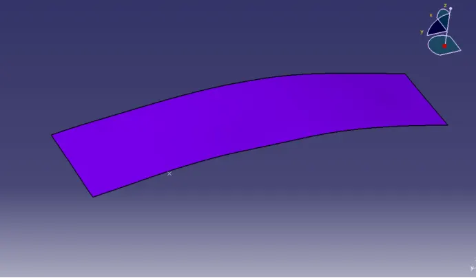
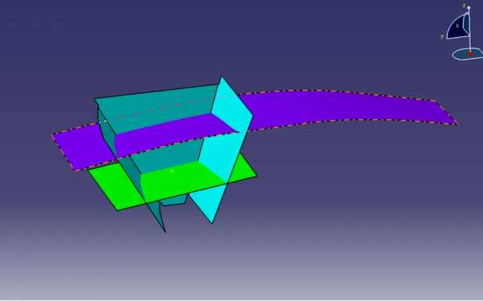
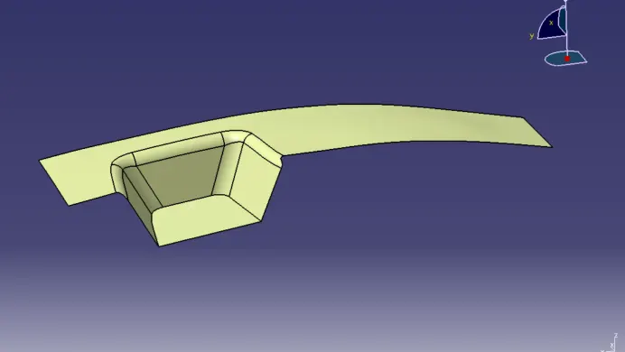
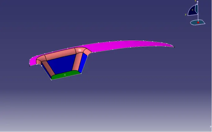
Trim the Walls, Base, and Bezel rest surface to get Class B and give edge fillets of R14 and R15 by calculating the fillet value. The Class B surface is given in the below image.
- Creating Class C surface from Class A & B surface -
Extract the boundaries of the Class A surface by using multiple extracts and make their smooth curves.
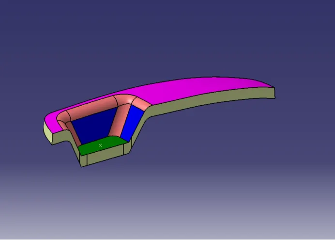
- Final join -
First of all, join the Class A and Class C surfaces together.
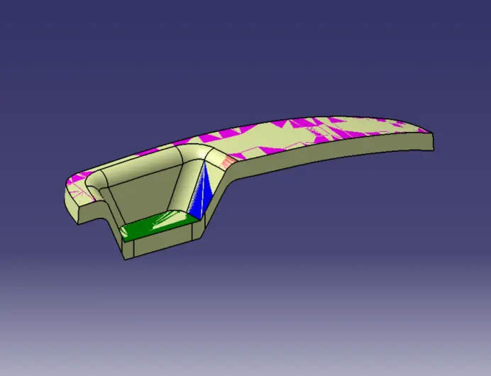
Then trim them with a Class B surface.
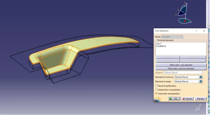
- Creating a solid body by using a closed surface -
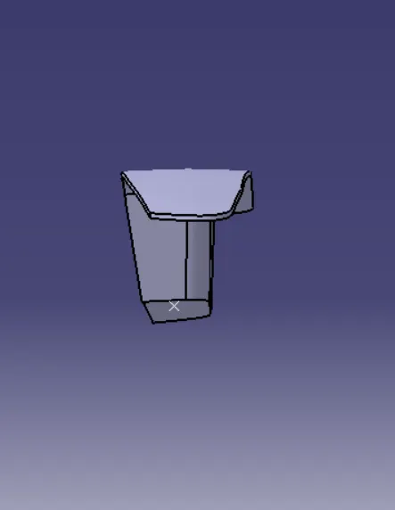
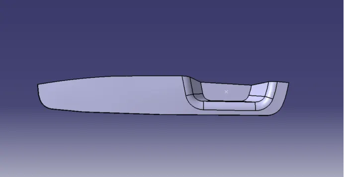
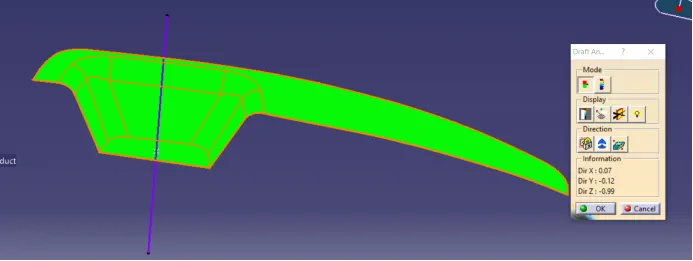
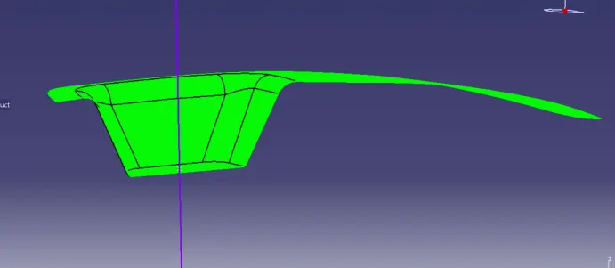
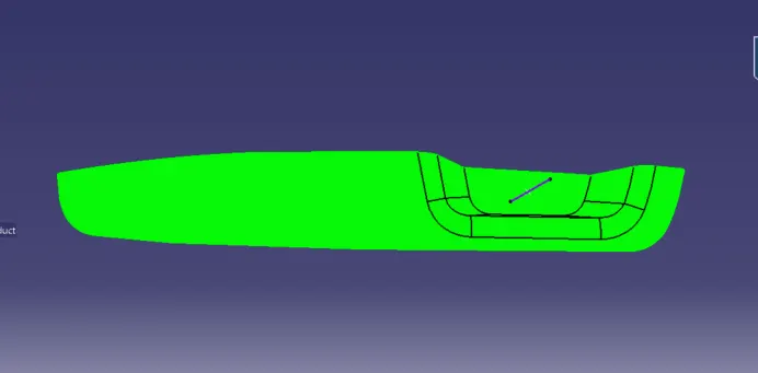
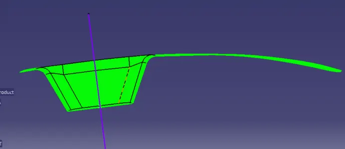
A solid body is created by a closed surface feature in the Part Design workbench in the defined part body. This is our design output shown as given below in various orientations(Isometric view, Front view, Side view & Top view).
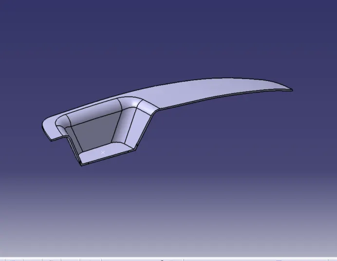
Views -
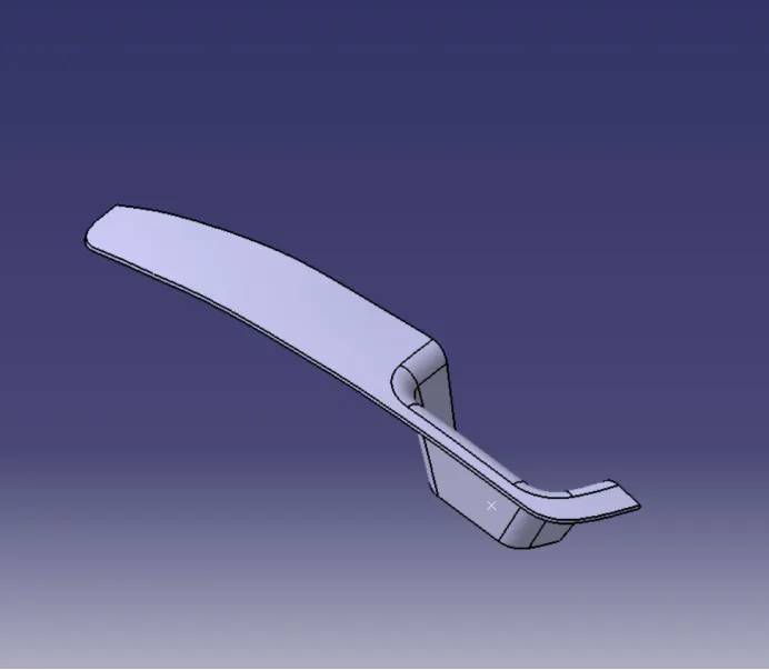
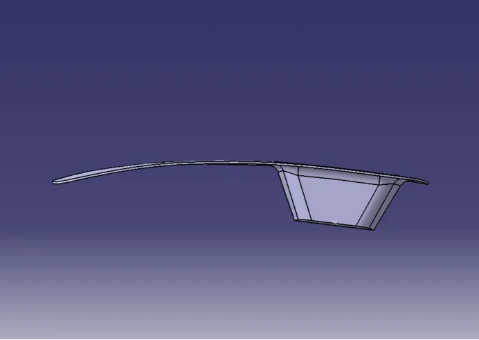
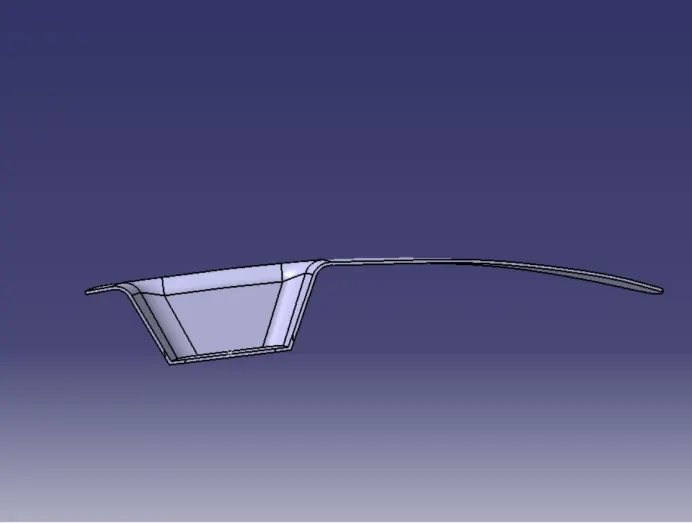
DRAFT ANALYSIS -
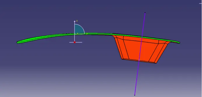
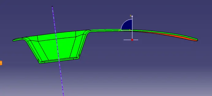
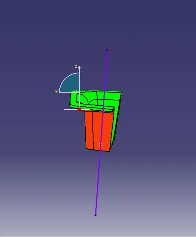
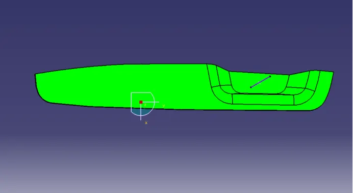
Class A surface -
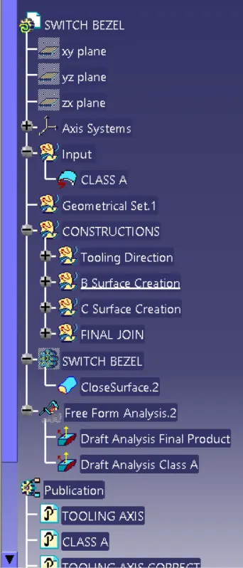
FEATURE TREE -
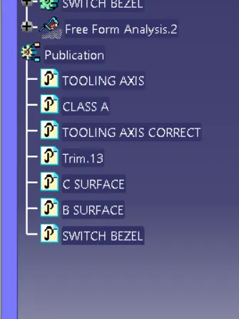
PUBLICATION -