Week 8 - Challenge 2 - Switch Bezel Design
- Screenshots of the Draft analysis report for both the given Class-A surface and the final plastic component
Class A surface Drafft analysis
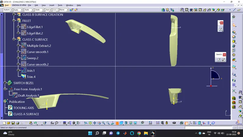
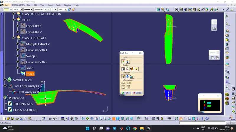
Draft Analysis of final plastic component
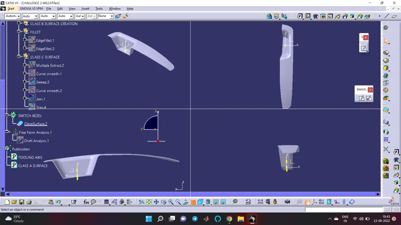
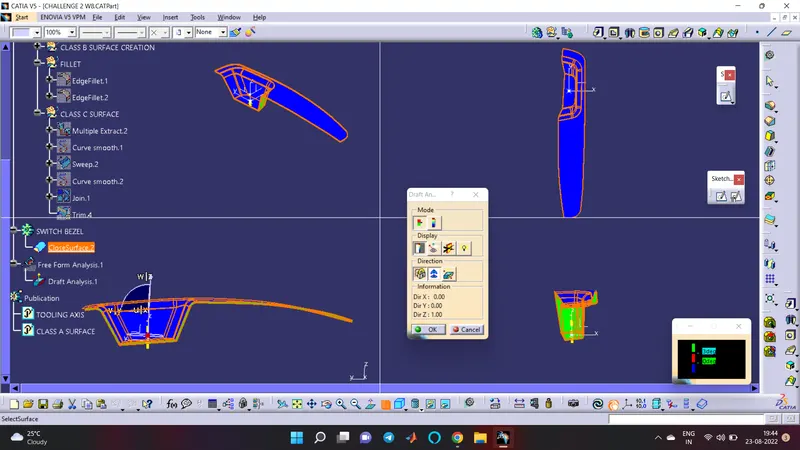
- Screenshots of the solid model with the proper color code of the draft angle in various orientations (Isometric, Front, Side, and Top View)
- Report
- A detailed report should be done explaining the draft analysis and the tooling axis creation.
Select the draft analysis then select the quick analysis mode then select the compass to the tooling axis, after that click anywhere on the Class A surface. A colour variation ca observes there its means that we have given a draft angle of 3 degree
So, the green colour represents the draft is more than three degrees
Blue colour represents the draft is between 0 and 3 degrees
The red colour represents the draft is negative or less than three.
- An explanation should be given on the way of creating the tooling axis, particularly the Bisecting method.
For creating the tooling axis here we only have the three walls so create a boundary then draw the two referance line then take the bisect of the bothlie and make the two lines as reference.then create a boundary on the otherside and draw a line, here only one wall is present so we need to create another line normal to the plane with an draft angle of 4 degree. so that we get two intersecting lines and then create a bysecting lines with reference to this line and thus the tooling axis is created. Change the colour and thickness of the tooling axis