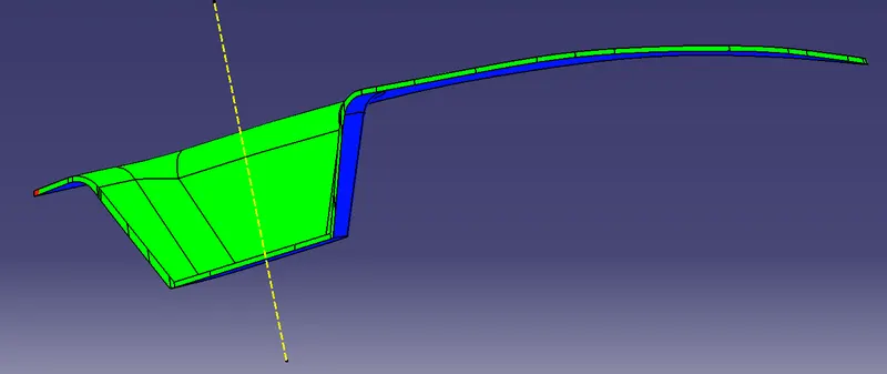
Week 8 - Challenge 2 - Switch Bezel Design
SWITCH BEZEL DESIGN:
Tooling axis: -
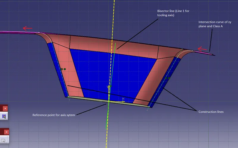
Switch bezel is a complex body part with no symmetry along a face or axis. The tooling axis of switch bezel is created by bisection method. The bottom face of bezel is extracted and a point is created in the middle of the extract. Using this point as reference, an axis system is inserted. The intersection of the planes and bezel gives us the boundaries which are required for the lines for tooling axis.
Using the intersection of zy plane and the bezel, the lines representing the two side faces of the bezel are constructed. These lines are then bisected by a third line.
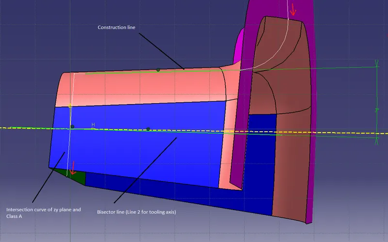
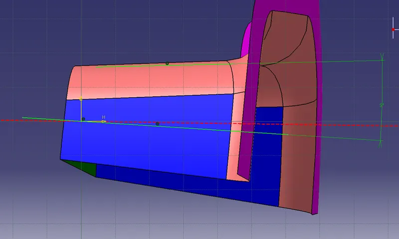
Then the intersection of zx plane and the bezel is taken, since this intersection has only one face bisection here is not possible. Therefore, the line has to be constructed by trail and error. The angle between the bisector line and constructor line is taken initially as 3-degrees.
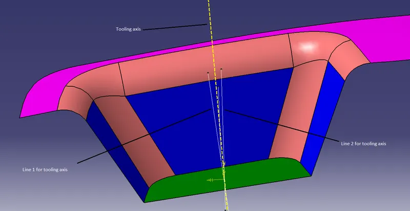
Using the two lines obtained in the zy plane and zx plane, a bisector line is created which bisects the above two lines. This line is the tooling axis of switch bezel. The confirmation of the tooling direction can be done only after the draft analysis of Class A surface as this is a trial-and-error method.
Draft analysis of Class A and final tooling direction: -
The draft analysis is done by repositioning and adjusting the compass to the tooling direction.
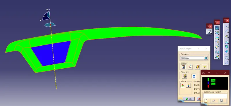
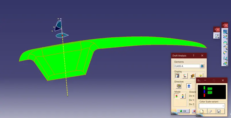
In the draft analysis we can clearly observe the blue colour of a face which indicates the draft angle to be less than 3-degree. For the Class A the draft angle is required to be always greater than 3-degree. Thus, the tooling direction is not acceptable and has to be changed by changing the angle between the lines in zx plane. The angle is now taken as 5-degrees. Again the draft analysis is done with the new tooling axis. This time we can see there are no faces that have draft angle lesser than 3-degrees. Thus, this tooling axis is selected as final tooling axis.
Class B surface: -
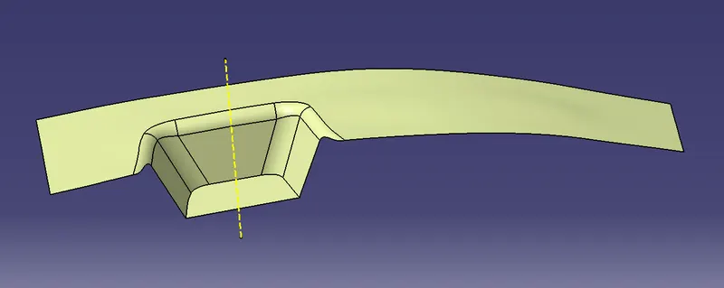
For creating Class B surface, the plane faces and the bezel rest face of Class A are extracted and untrimmed. Then observing the intersection of untrimmed surfaces are extrapolated accordingly. For finding the radius of fillet faces the faces from Class A are extracted and untrimmed, then measured for their radius. Directly from Class A, the radius of the faces cannot be measured as they are intersected by other faces at angles. After that the faces are trimmed, offsetted and filleted accordingly and Class B is obtained.
Class C surface: -
Class C is created by the boundary of Class A using the boundary and sweep commands. The angle to the Class C is given from the draft direction as 5-degrees.
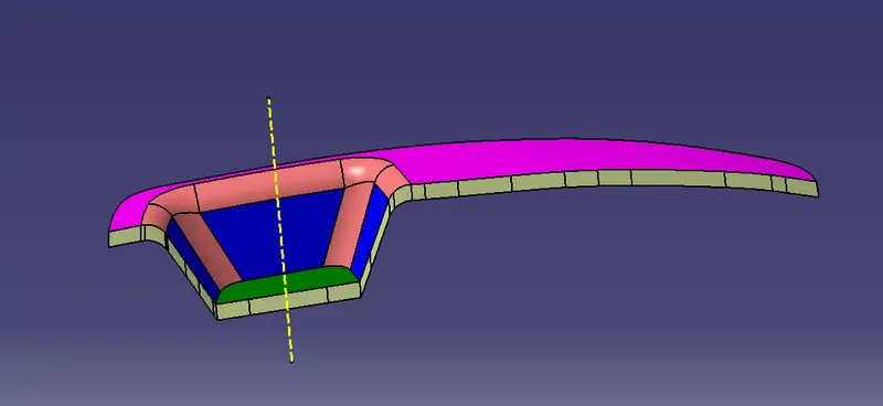
The surface for solid part is generated by joining Class A and Class C and trimming with Class B.
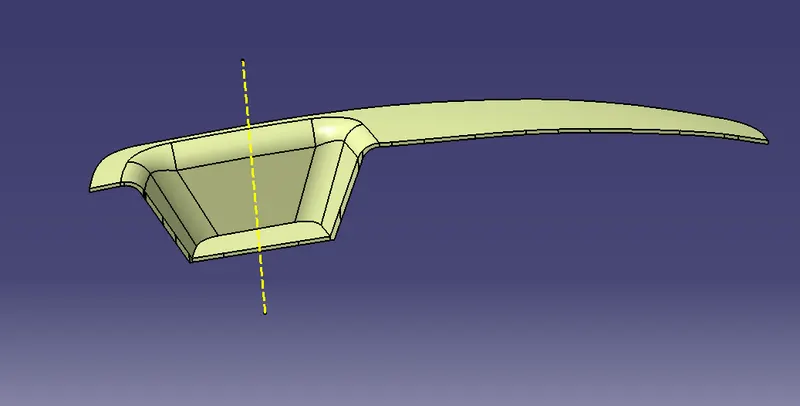
Plastic part draft analysis: -
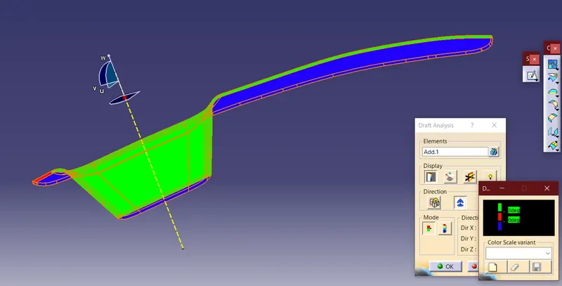
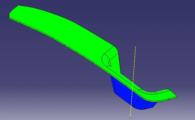
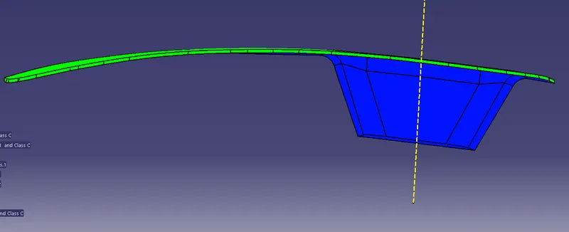
The draft analysis of the part body which is obtained by close surface shows that Class A has above 3-degrees draft everywhere and Class B has negative draft which is expected. Class C has less than 3 degrees draft at one end, this can be attributed to the tooling direction of the bezel which was achieved by trial and error. This issue can be resolved by adjusting the tooling direction and changing the angle of Class C with respect to the tooling direction.
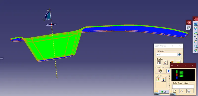
After adjusting, we observe just a patch of red at the Class C surface, further adjustment is not possible due to constraints. Thus, we can infer that
a. more advanced methods are required for the optimized tooling direction
b. the small patch can be treated as margin of error and can be neglected
c. a fillet can be provided at the location of the patch so that its aesthetically good and resolves the drafting issue
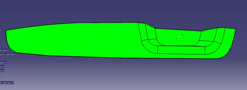
Various orientations of the part are given below
Isometric view
Front view
Top view
Left side view
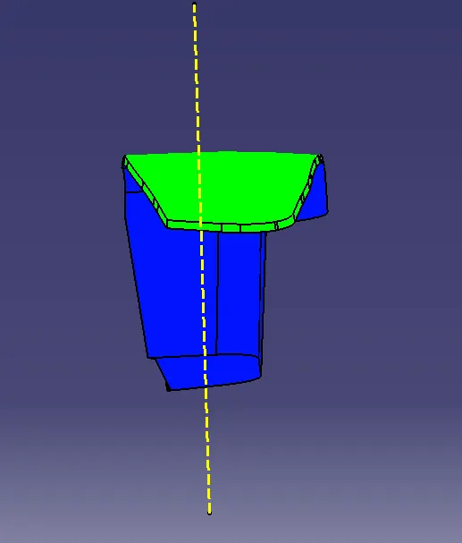
View showing red patch and the part body