Week 8 - Challenge 2 - Switch Bezel Design
AIM
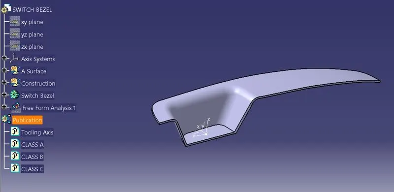
To create the Switch Bezel Plastic component through the given Class-A surface.
REPORT
1. Creation of Tooling Axis
- At first we identify the proper location for the tooling axis to pass through. In this model we find the base of the switch besel to be the ideal surface for tooling axis.
- So using 'multiple extract' we first extract this surface.
- Then we create a point on centre of this surface using point option.
- With this point we create an axis system.
- Looking at the model we identify that tooling can be done through both y and z axis.
- So we first take the yz plane as the reference and using sketch we create a dummy tooling line with respect to the two side walls
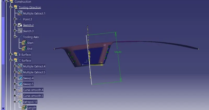
- Then using the zx plane we create another dummy tooling axis.
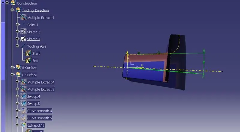
- Using the bisecting lines option we bisect both these dummy tooling axis to form the required tooling axis.
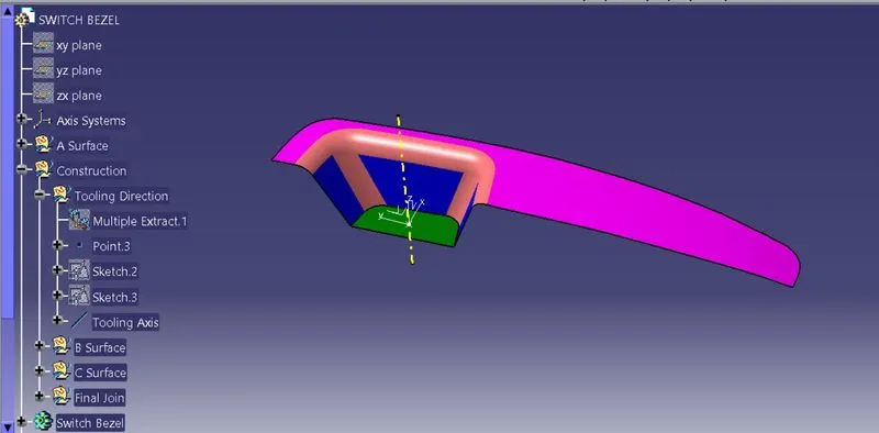
2. Draft analysis on Class A
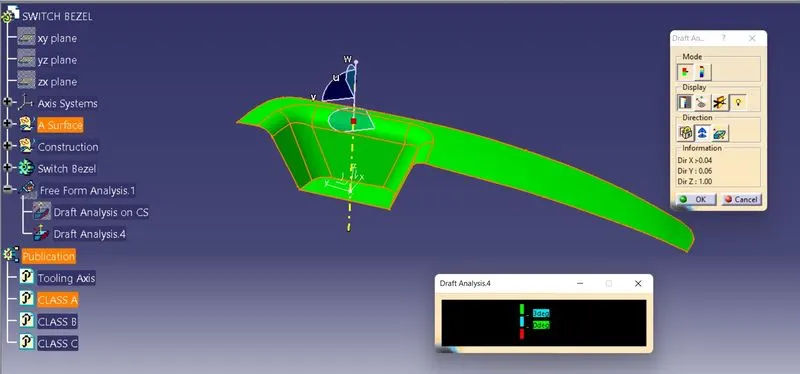
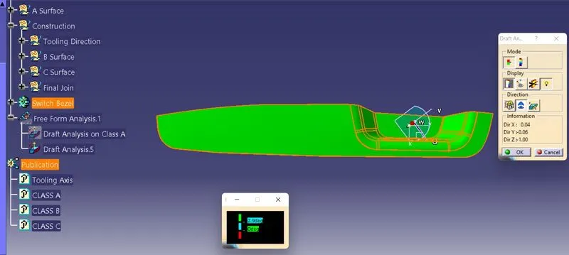
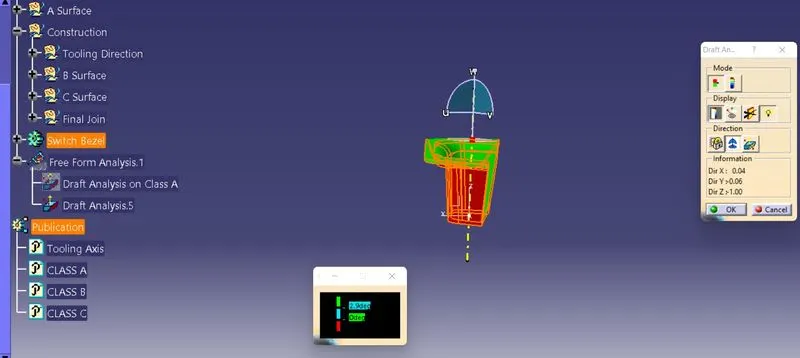
- We select the draft analysis option and analyse it on class A
- From the analysis, it shows that the class A is having a draft angle more than 3 degrees which is as per required.
3. Creation of Class B surface
- First we extract the bezel rest surface using extract option.
- Then we untrim the surface
- Then we offset it to 3mm.
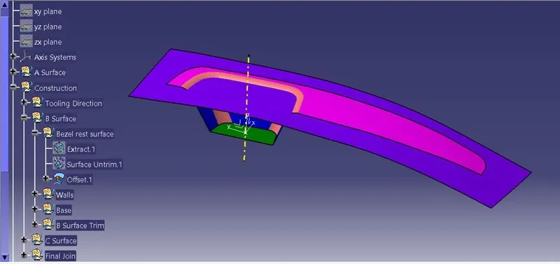
- Then we extract the walls of the class A as shown below:
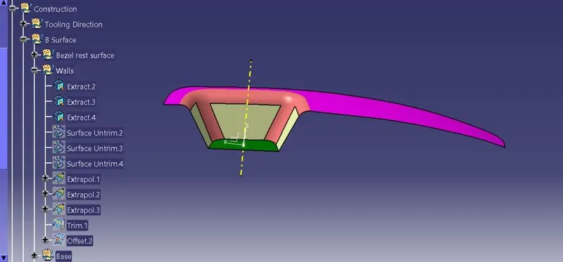
- Then we untrim all the wall extracts.
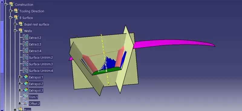
- Then we trim all these surfaces together and offset it for 3mm.
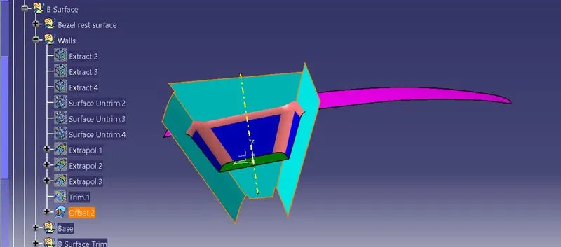
- Then we take the extract of the base surface.
- Then we untrim it.
- Then it is extrapolated.
- After which, it is offsetted for 3mm.
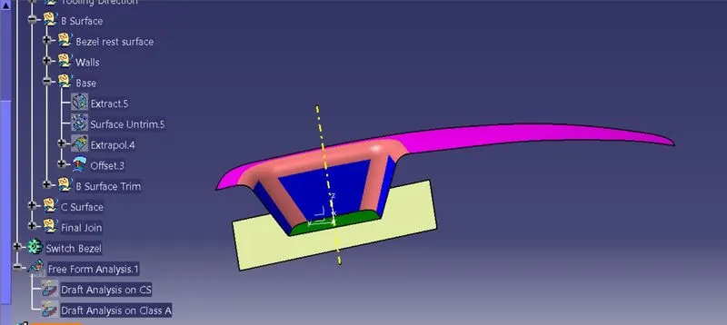
- Then we trim the bezel rest surface with walls.
- Then we again trim that with base.
- Proper edge fillets are applied to form the class B surface.
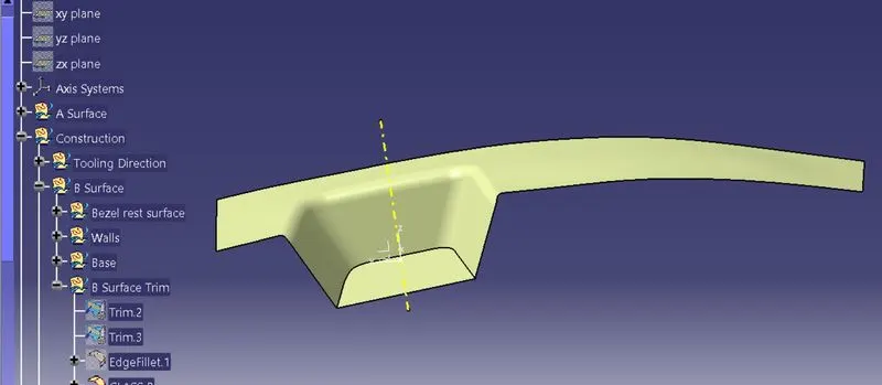
4. Creation of Class C surface
- Using multiple extract we extract the boundaries of the class A surface
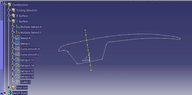
- Using sweep option we extend these boundaries to certain amount.
- Then using curve smooth option we smoothen the surface.
- Then we extrapolate the edges of the sweeps and trim them. Thus forming the class C surface.
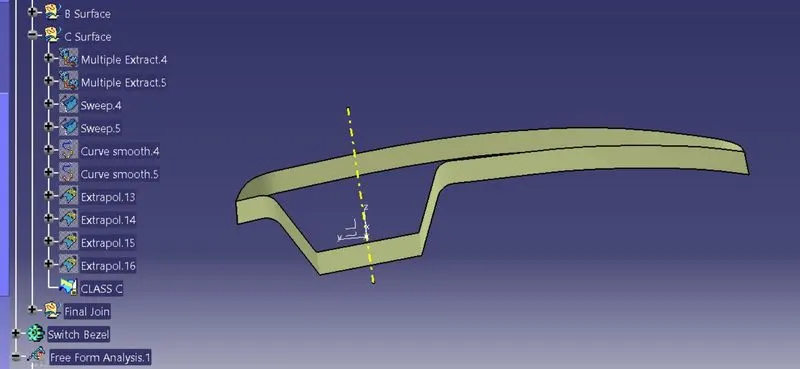
5. Final join
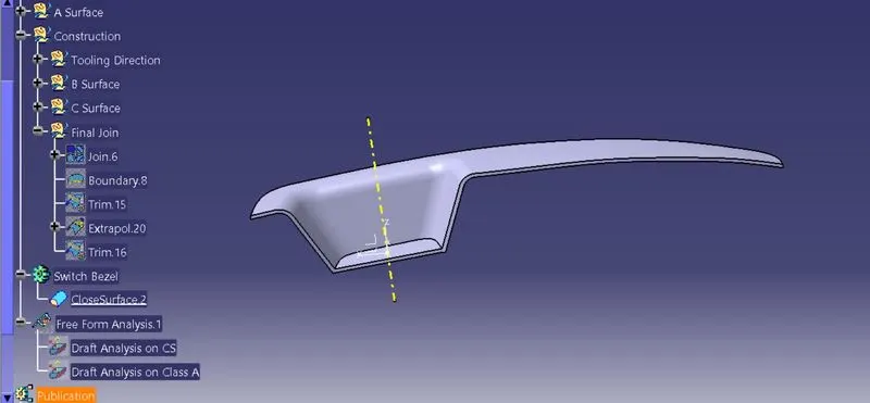
- Once we created class B and C surfaces, we use join command to join Class A and Class C
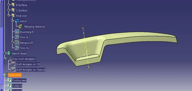
- Then we trim this joined surface with Class B to form the final part.
- We use boundary option to check weather its a closed body.
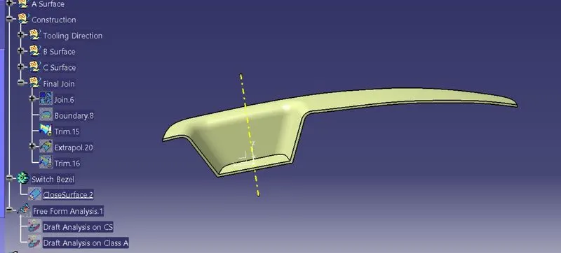
6. Closed Surface
- We then swutch to part design to create a final platic component using closed surface option.
7. Draft analysis on final platic component
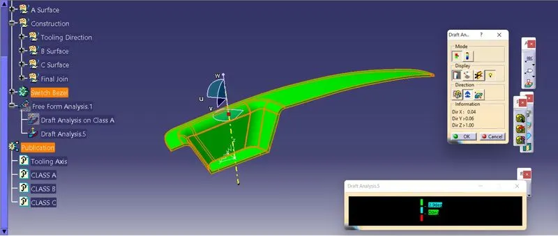
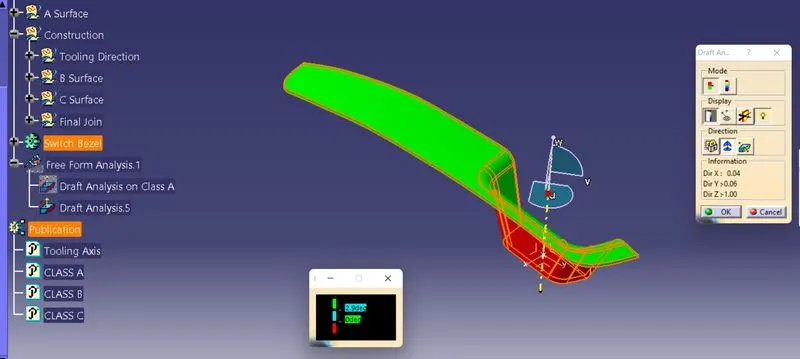
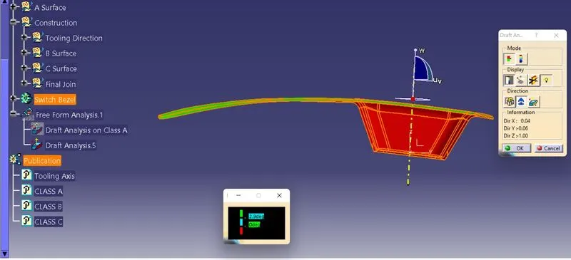
- The draft analysis on this shows that it is at an draft angle greater than 2.9 degrees.
RESULTS
1. Isometric view
2. Front view
3. Side view
4. Top view