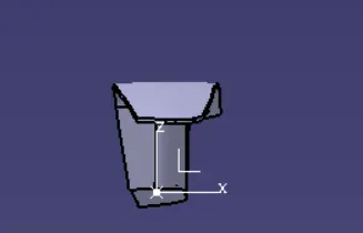
Week 8 - Challenge 2 - Switch Bezel Design
Aim:
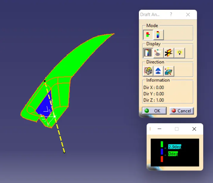
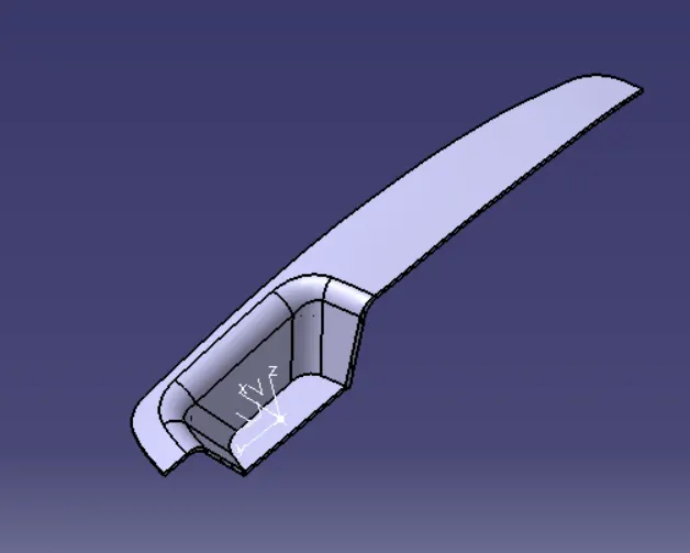
To create the Switch Bezel Plastic component through the given Class-A surface. To begin with, the tooling axis for the given Class-A Surface should be created meeting the requirements of the draft angle and at the end perform the Draft analysis on the model.
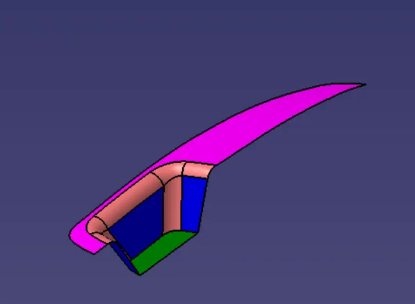
Given Model:
Tooling Direction:
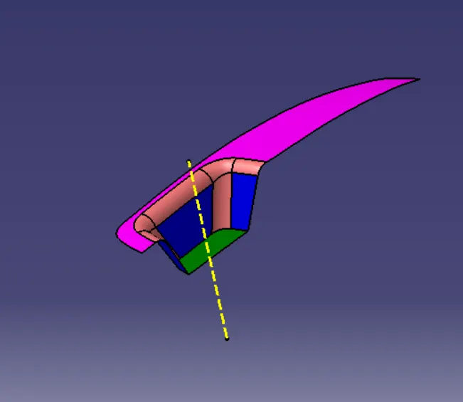
Extract base from class A surface and created one point on the surface, based upon point created one axis system.
Taken YZ plane created one sketch and based on sketch created one bisecting line.
Taken ZX plan again created one sketch, based on sketch created one line ,refer below image.
Two lines created already, now create a bisecting with respective two lines. This bisecting line is the tooling direction.
Draft Analysis:
Class B and C surface creation:
Class B Surface:
Extract bezel rest surface and used untrim option to take full surface after that offset the same 2.5mm downward.
Again, Extract Class A surface wall and untrim all the wall.
Extrapol all the surface 50mm with Point continuity and offset them 2. 5mm.Then trim them for getting required surface.
For Base also used same operation after than all the surface trim to get required surface.
Given required edge fillet.
Class C Surface:
Create a boundry using the given class A. Now with the sweep option we can create a surface wall aong the tooling direction with an angle of 3 deg outward.
Now trim class B with class C
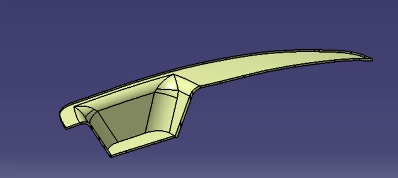
And then to get final surface trim it with class a.
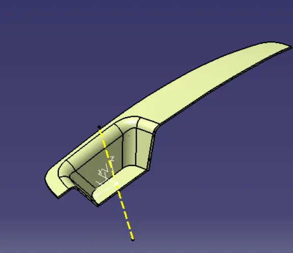
Now use the closed surface command in the part workbench to create a solid body from the final surface.
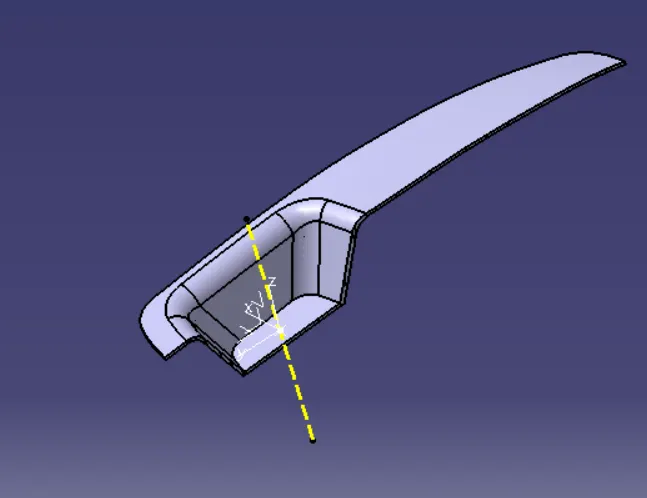
Perform Draft Analysis on the final model.
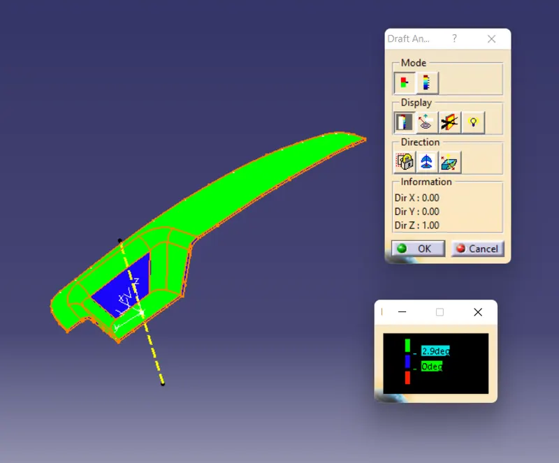
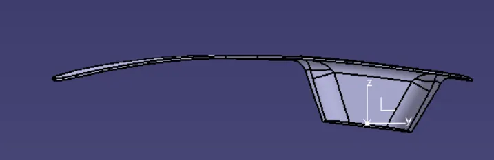
This is the result obtained for the given class A model. The class A model itself having some issues with the Drafting analysis.
Isometric View:
Front View:
Top View:
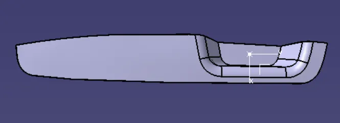
Side View: