Week -2
1.
To make a simulink model of adoor bell uing solenoid block.
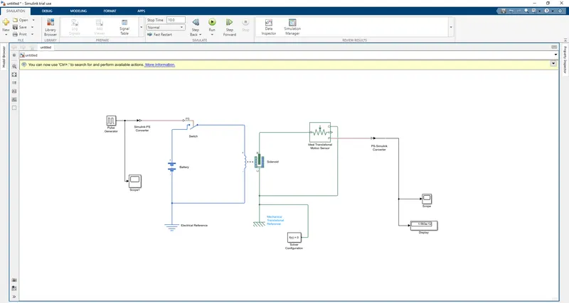
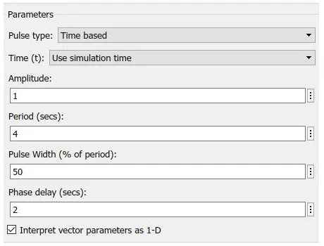
A pulse generator block is used to create square wave pulses at regular intervals .It is connected to Simulimk- Ps converter block and then to a switch block. Scpe is attached to the pulse generatoe to plot the results. The Amplitude, Period, Pulse width and Phase delay are the parameters of the pulse generator which needs to be changed to get the desired output waveform.
The swicth block is controlled by the pulse generator.If the external signal is greater than the threshold parameter the switch is closed or else it will be in open state. The positive terminal of the battery is connected to the switch. Where as the negative terminal of the battery is connected to the electrical reference. The electrical reference acts as a ground to the circuit.The battery is connected with the solenoid block thus completing the circuit. The mechanical reference is connected to the port c of the solenoid. The port r of the solenoid is connected with ideal transational sensor to observe the plunger movement. The prt P is connected through a PS - Simulink converteran to the scope to get the results.Mechanical transational sensor is connected to the solenoid. Solver configuration block is added to the model which specifies the solver parameters before simulation.
OUTPUT:
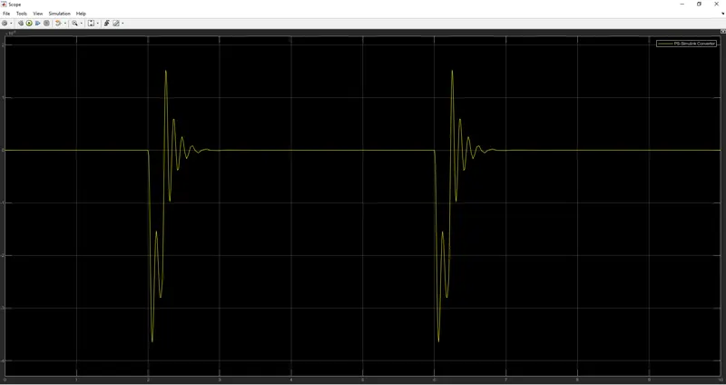
The plot obtained from the scope.
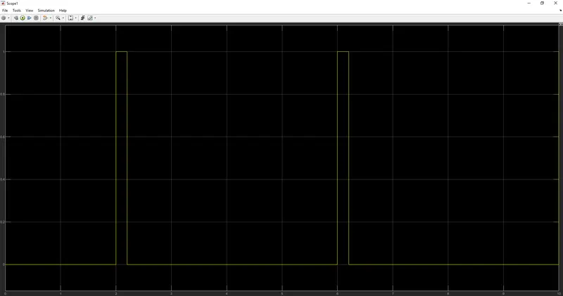
Frequency of the pulse from the pulse generator
2.
The Inputs are :
Temperature source: 20 °C from 0 to 10 seconds
27 °C from 10 to 30 seconds
23 °C from 30 to 50 seconds
Fan conditions: ON if the temperature above 25 °C, OFF otherwise
Simulink Model :
BLOCKS USED :
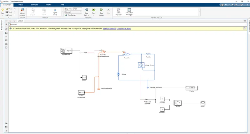
Signal builder, Scope, Solver configuration, Simulink - Ps coverter, Ps - Simulink converter, Controlled temperature source, Battery, Thermal reference, Electrical reference, Thermistor, Resistor, Voltage sensor, Constant block, Switch block and display.
EXPLANATION :
Signal builder block is used to give the input signals to the model based on the given conditions. It is connected to the port B of the controlled temperature source block which acts as the temperature source for the model. Port a is connected to the thermal reference and the solver configuration block.
The temperature source is connected to the Thermistor. Thermistor is a device whose resistance is dependent to the temperature. Battery and a resistor is connected to the circuit along with a electrical reference . Voltage sensor is used to measure the voltage flow in the circuit.
The output of the sensor sends physical signal which needs to be converted by the coverter block and then to the switch block as well as a dispaly block . The switch block consist of three input ports . The first and the last ports are connected to a constant block whose values are assigned to be 1 and 0. The first and last are the data ports the second one is the control port. The inputs are passed through based on a certain criterion to the scope.
RESULTS :
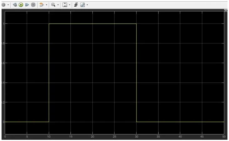
On the first 10s the fan will remain in OFF condition because the temperature is below the threshold temperature. The next 20s the temp goes beyond the threshold temperature an the switch is ON. In the last 20s the temp reaches 296 kelvin which is less than the threshold temp and the fan will be in OFF condition.