Week 8 - Challenge 2 - Base Bracket Design
BASE BRACKET DESIGN
Aim: To create a base bracket plastic component through a given class A surface and perform draft analysis on the final component.
Objectives:
- create a class-B and class-C surface.
- create a solid component through a class A surface modeling.
- create a tooling axis on a base bracket using the bisecting line method.
- create a final plastic component and perform a draft analysis on the class A surface and the final component.
Class-A surface: the class-A surface is the outermost surface of the plastic component and it is the aesthetic surface that the designer creates as an input work.
Class-B surface: the surface that has a specific thickness from the class-A surface is the class-B surface. This is the surface that contains all the engineering aspects of a model.
Class-C surface: a surface that joins class-A and class-B surfaces is a class C surface.
Class-A surface is given as an input to create a final solid component.
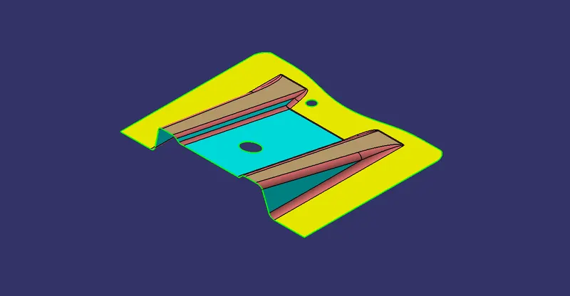
The first step is the creation of the tooling axis the direction in which the mold opens or the core and cavity open visually gone check the best possible tooling direction on the class A surface. and perform the draft analysis.
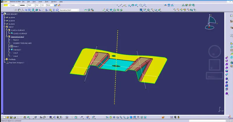
here, we are selecting the z-direction as the best possible tooling direction to create the tooling axis as we can see 2 holes and a flat surface
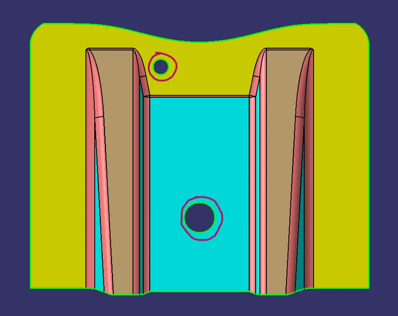
make an axis system and intersect the zx plane with the class A surface. As the result gets 2 lines on zx
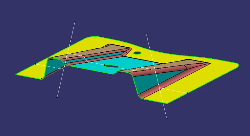
here we can see in the picture that we have created two lines, now we will bisect the lines and choose the proper direction, here vertical direction. this will be our final tooling axis
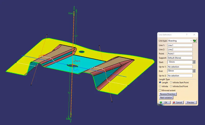
Draft analysis:
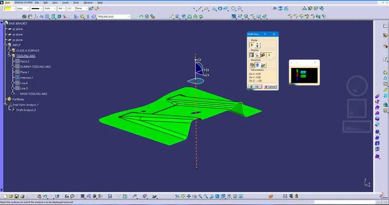
- To perform draft analysis set a customized reader style.
- select the draft analysis tool.
- Adjust the draft direction to the molding axis using the compass.
- click on the surface and see that the surface is within the permissible limit of the draft values.
observe the color ranges:
- green: draft value above 3 deg.
- Red: below 0 degrees.
- Blue:0-3 degree.
To create a Class-B surface:
initially, we have to extract the right side rib from the class A surface using the extract option the same way as the left side rib was also created.
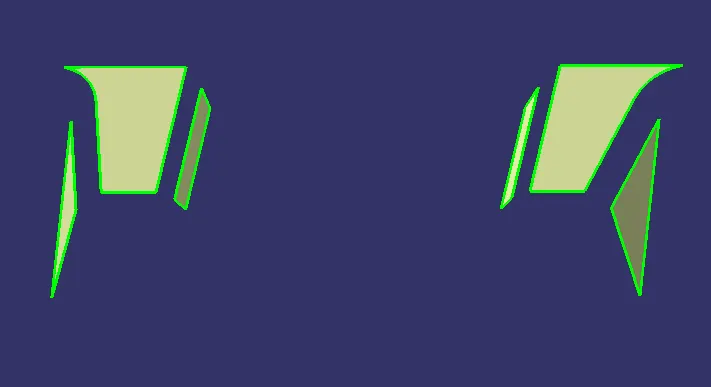
now, untrim them to obtain the original parent surface. using the untrim option.
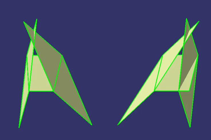
extrapolate both the ribs and perform the trim operation to obtain the required surfaces
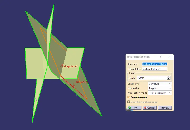
then offset the surface to get the required thickness.
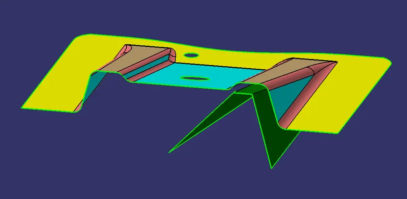
similarly, create the left side rib
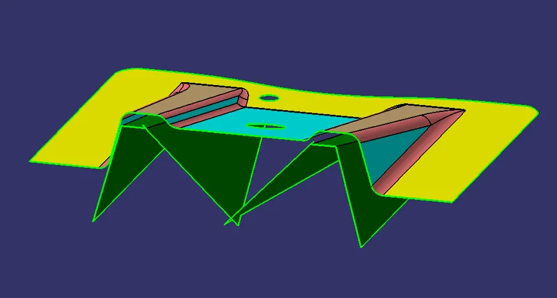
now similarly extract the slant surface untrim the surface extrapolate it and offset to the required 2.5mm
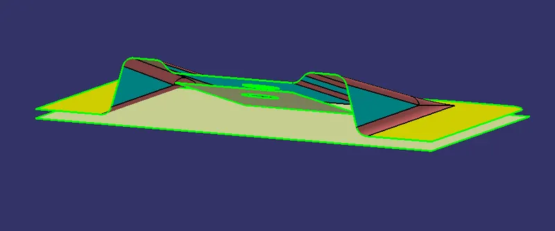
once offset 2.5mm all the surfaces are trimmed to get the exact shape of the class-A surface below 2.5mm. apply the fillet to the required area (filleting = fillet value + thickness) if the offset is below. here we finished surfacing the class- B surface.
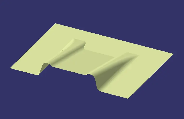
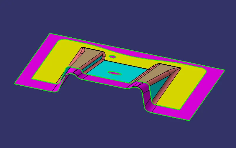
To create a class- c surface:
we have to extract the boundary of the class A surface. and then extract the holes on the class-A surface.
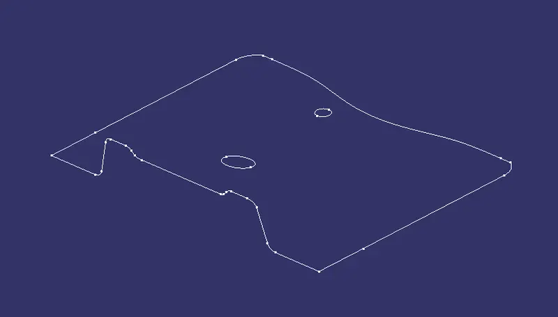
use the sweep command on the boundaries one by one to get the class- C surface. select with the draft direction option and set a 3-degree draft angle to create a sweep and select direction as tooling axis z-direction.
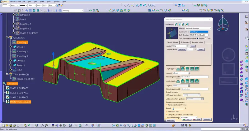
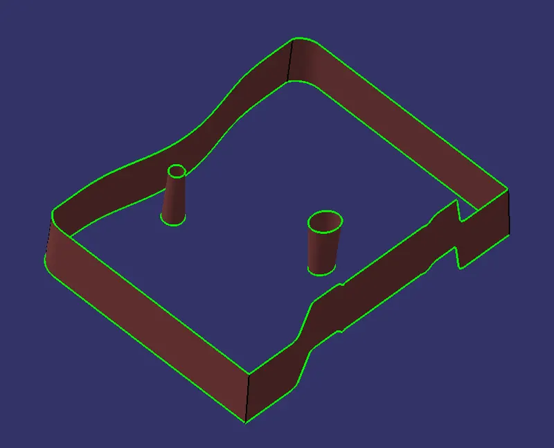
join all the surfaces using the join command to create a single body and make sure there is no boundary between class A and class B
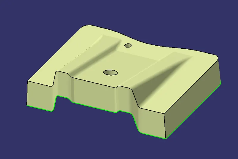
Trim the class-B surface with the join created earlier.
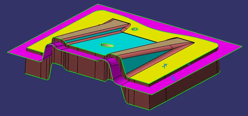
as a result, the class C surface is created.
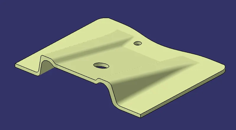
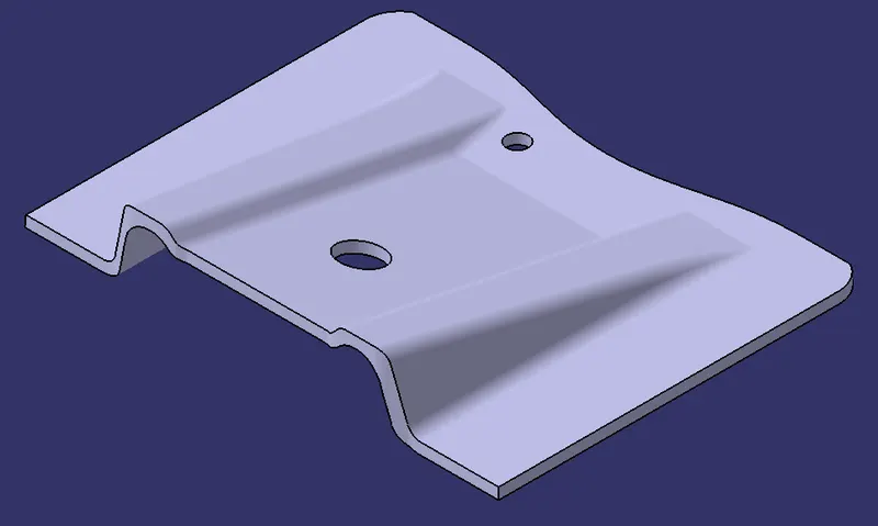
After the class-C surface is created Define the part body and go to the part workbench and apply the close surface command to make it a solid body.
 .
.
Draft analysis on the final component:
Quick analysis mode color codes
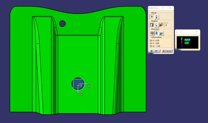
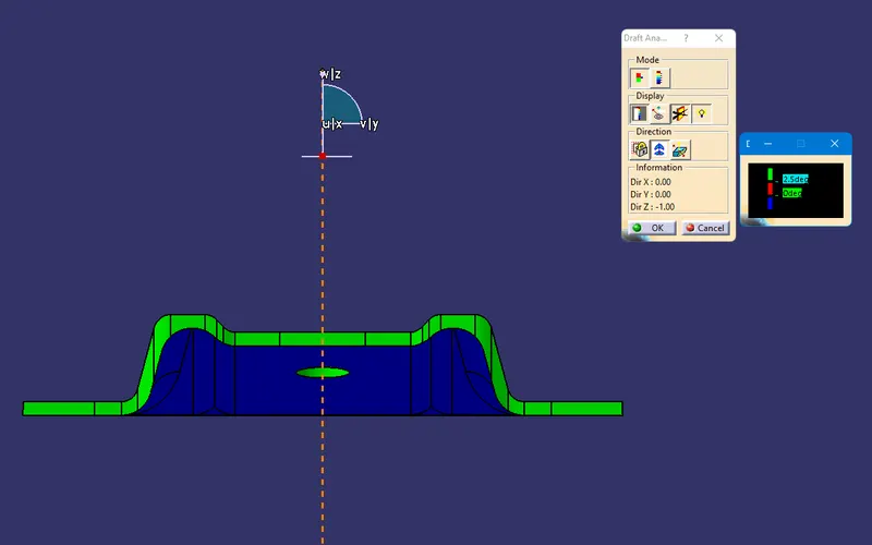
- green: a draft value above 3 deg.
- Red: below 0 degrees.
- Blue:0-3 degree.
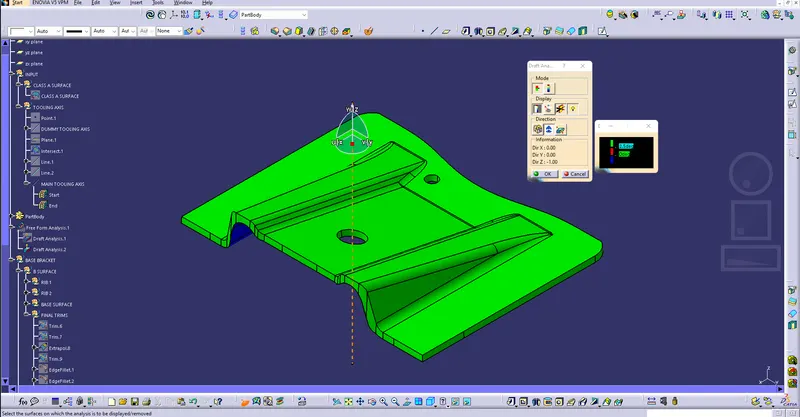
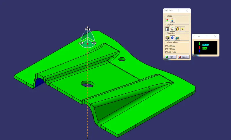
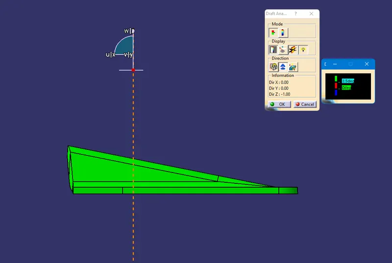
The above picture shows the class A surface and class c surface both clearing the draft angle at 2.9mm. as the result, we performed the draft analysis successfully on the class c surface.
ISOMETRIC VIEW
SIDE VIEW
TOP VIEW
FRONT VIEW
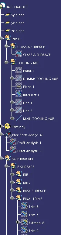
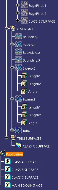
FEATURE TREE
 .
.